
Now, let’s take a look at the code:
//———————————————————————————————————
//Programmer: Syed Tahmid Mahbub
//Compiler: mikroC PRO for PIC v4.60
//Target PIC: PIC16F877A
//Program for phase angle control
//———————————————————————————————————
unsigned char FlagReg;
sbit ZC at FlagReg.B0;
void interrupt(){
if (INTCON.INTF){ //INTF flag raised, so external interrupt occured
ZC = 1;
INTCON.INTF = 0;
}
}
void main() {
PORTB = 0;
TRISB = 0x01; //RB0 input for interrupt
PORTA = 0;
ADCON1 = 7; //Disable ADC
TRISA = 0xFF; //Make all PORTA inputs
PORTD = 0;
TRISD = 0; //PORTD all output
OPTION_REG.INTEDG = 0; //interrupt on falling edge
INTCON.INTF = 0; //clear interrupt flag
INTCON.INTE = 1; //enable external interrupt
INTCON.GIE = 1; //enable global interrupt
while (1){
if (ZC){ //zero crossing occurred
delay_ms(2);
PORTD.B0 = 1; //Send a pulse
delay_us(250);
PORTD.B0 = 0;
ZC = 0;
}
}
}
There isn’t much to it. The zero-crossing is first checked. After zero-crossing occurs, a small delay is present before the triac is fired. Here, I’ve used 2ms. So, the triac is fired 2ms after the zero-crossing occurs. The gating signal is removed 250µs after that. 250µs is enough time to ensure that the triac has turned on. Even though the gating signal is removed, the triac stays on until the next zero-crossing as it is a latching device. Now you may ask, why remove the gating signal? Just keep it on till the next zero-crossing. Well, that’d work too. The problem there would be that, there would be high switching losses of the thyristor. The gate drive resistance would dissipate immense amounts of power – all for no reason, since the triac would be on even if the signal was removed.
The rest of the code should be easy to understand and should be self-explanatory – I’ve added comments to help you understand.
Now let’s take a look at my circuit setup and then the output waveform using this code:
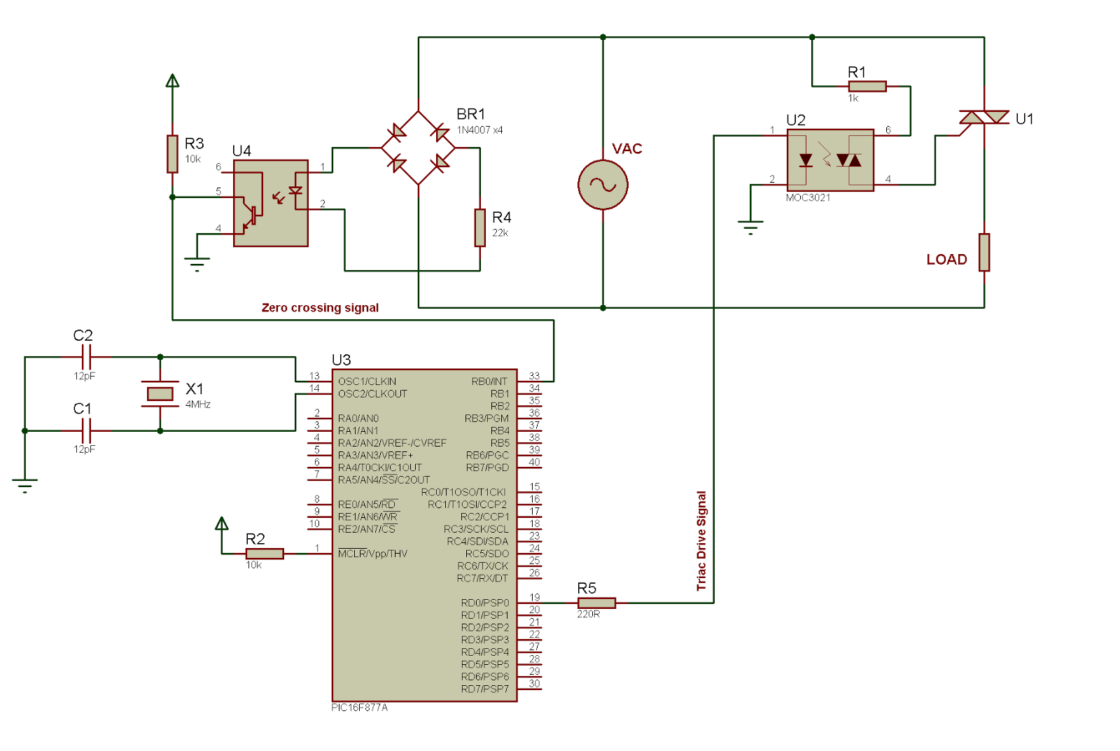
Fig. 1 – Circuit Diagram (Click on image to enlarge)
You should choose R1 depending on the gate current requirements of the triac. It must also have a sufficiently high power dissipation rating. Usually, the instantaneous power may be very high. But since current flows through the resistor for only 250us (1/40 of a 50Hz half cycle), the average power is small enough. Usually, 2W resistors should suffice.


