
Building Your Own
The aim is to build a reliable function generator that can go up to 1MHz in frequency, up to 9V in amplitude, and that allows you to choose between sinusoidal, triangle, and clock (i.e., rectangular with 50% duty cycle) signals. To help you understand why I chose the components used, how they work together, and how the firmware was written, I am going to split this article into two big chunks, the hardware and the software.
Hardware
There are two main parts regarding the hardware aspect of this build: the power supply and the main PCB containing the function generator IC and the microcontroller.
The Power Supply
The main PCB will need two voltage rails: +12V and -12V. The symmetrical supplies are needed for the final amplification of the signal. A smaller +5V rail will be created directly on the main PCB by regulating the +12V one; it is needed to power the microcontroller, the AD9833, the function generator IC, and finally the 24MHz crystal oscillator. Below you can find the schematic of the power supply board:
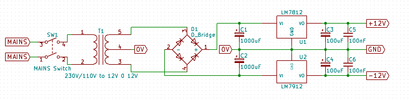
To obtain these voltages, a transformer will be used, from 230V or 110V (depending on your region) to two 12V AC lines (on the transformer it will usually be written something along the lines of 12V-0V-12V). An output current of 200mA is more than sufficient.
Remember that the output of a transformer is AC and we need DC. For this, we will be using a simple rectifier bridge. This will change the sinusoid into a positive signal. These usually come as standalone components but you can alternatively use four general purpose diodes such as 1N4001.
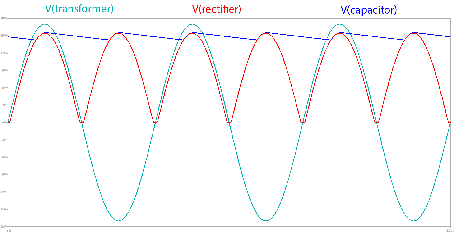
We will not be using it in the standard configuration as we want a symmetrical output, so we will connect them as in the schematic above: the ends of the transformer are connected to the rectifier, and the center tap is connected to ground. To smooth out the output we will first use two large capacitors, each 1000µF rated at 35V. Below you can find the output waveforms for the power supply rails at various stages:
In addition, to remove the ripple, two voltage regulators are used, the classic LM7812 and its sibling the LM7912, which is used for negative voltages. To top it off we add a 100µF capacitor and a 100nF one, both rated at 25V, to each regulator IC output. We want this supply to be as smooth as possible, as we will be using them to offset our final output voltage, and any AC components will propagate to the output.


