
We will give a practical example: let’s assume that the load (after the converter, we will talk about it later) absorbs 800 mA at a voltage of 5 volts, and that the converter has an excellent efficiency (about 90%), which is close to the actual one in our circuit. We will also suppose that the Schottky diodes present a voltage fall of about 0.5 volts. By powering everything by means of the PWRIN plug with a voltage of 15 volts, we will obtain a current absorption of:

It is immediately possible to notice the great advantage of using a switching power supply: the absorbed current decreases with the input voltage increasing, differently to what occurs with the linear regulators that are used by the Arduino series, in which the absorbed current remains identical to the supplied one and, being multiplied for the input/output voltage fall, it causes a significant thermal dissipation on the part of the regulator.
In the formula, the diode’s voltage fall has been considered, (0.5 volts), which brings the total efficiency to:
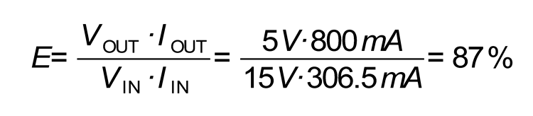
against a theoretical 90%, given by the converter. Therefore, the diode causes an efficiency loss of 3%, that we may consider as negligible. It is possible to notice from the formula that the impact of the voltage fall on the diode increases as the input voltage decreases, which is logical since the switching transfers the power, converting its voltage and current: as the voltage increases the current decreases and vice versa.
Let us make the same calculation, now, by using an input voltage of 3.6 volts (a value that is close to the one of the LiPo battery):

As a first thing we may see that, in order to obtain 800 mA as an output, we have to draw no less than 1.433,7 mA from the input; the actual efficiency tehrefore becomes:

In this case, the voltage drop on the diode brought to an efficiency loss of a whopping 12.5%, and right when a greater efficiency would be needed, given that we power the board by means of batteries.
Moreover, a 0.5 volts fall on the diode, with a 1.4 amperes current, would correspond to a dissipated power of 0.7 W, that on a small size component would bring a considerable temperature increase.
The MOSFET, on the other hand, does not have a fixed fall at its ends, but it presents – when conducting – a resistance that depends on the component used; in our case it is worth 100 milliohm, at best.
The calculation gets a bit more complicated here:

which is a second grade expression in ILiPo; by inserting the values and by solving it, you will obtain:

A current that is well below the 1.433,7 mA in our previous case. With such conditions the efficiency becomes:

Therefore the MOSFET causes a loss of the 3.2% only, against the 12% of the diode.


