
Battery charge indicator circuits are very useful modules for efficient use of the Li batteries. These kind of indicators generally measures the voltage in the battery and indicate the charge by turning up any appropriate LED’s. But its not necessary you have to buy one of these modules to use your Li battery in a effective way. In fact you can build one with minimal components and little sweat.
Li BATTERIES:
Li batteries proves to be very useful source of power but for long lasting performance you need to look on to key parameters carefully. Li batteries should be used in such a way that always 20% of the battery’s charge is left before recharging it. Failure to that may cause the battery dead, so now you would’ve known that knowing the charge in the battery is very necessary to keep the battery alive. Let’s design a simple circuit to know the percentage of charge in a battery.
I am going to take a 12V Li battery and keeping it as an example , the design the battery charge indicator circuit is explained below. Now for a typical 12V battery the voltage at various charge levels will be
| Voltage measured | Charge Level |
| 13.5V | 100% |
| 12.5V | 75% |
| 11.5V | 50% |
| 10.5V | 25% |
You can find these details in the datasheet of the manufacturer, almost all 12V batteries carries the same properties but datasheet is always worth looking for.
BATTERY CHARGE INDICATOR DESIGN:
WORKING AND CALCULATION:
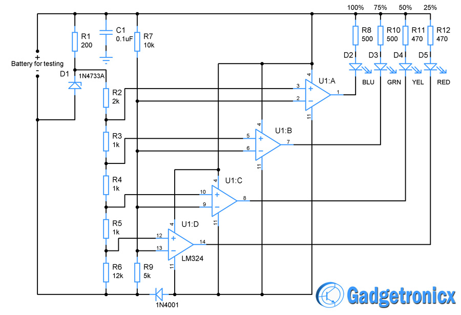
The Voltage measured to the corresponding charge levels forms very important reference to the above circuit. For easier understanding let’s analyze the circuit in a step by step manner. Initially connect the battery for charge testing to the circuit. Once it is connected a 1N4733A a 5.1V, 1W Zener diode is used to regulate the voltage along with a series resistor R1 which controls the current flow through zener. Thus we obtained a output voltage of about regulated 5.1V from the battery.
A quad Opamp IC LM324 was used as an comparator or activator for the charge indication LED’s. We have used U1:A with Blue LED for 100% indication, U1:B with Green for 75%, U1:C with Yellow for 50% and U1:D with Red for 25% of charge level. Using the status of the LED’s the charge level of the battery is determined.
The next step is to fix the reference voltage for each charge levels 100%,75%,50% and 25%. In order to fix the reference voltage for these charge levels a simple voltage divider is constructed using the resistors R2,R3,R4,R5 and R6. The voltage obtained from these dividers in turn feeds the reference voltage to the individual Opamp U1:A,U1:B…U1:D. The calculation for fixing the reference voltage for U1:A as follows
Vout = (R3+R4+R5+R6) * Vin / (R2+R3+R4+R5+R6) – Voltage divider formula
= 15K * 5.1V / 17K
= 4.5V
So the voltage reference for 100% of battery charge is fixed as 4.5V. For fixing 75% of battery charge the voltage divider equation takes the form
Vout = (R4+R5+R6) * Vin / (R2+R3+R4+R5+R6)
= 14K * 5.1 / 17K
= 4.2 V
4.2V is the reference voltage to the Opamp U1:B which is for 75% of battery charge indication. Repeating the above procedure gives 3.9V for 50% to U1:C and 3.6V for 25% to U1:D. We have now fixed the reference voltage for the Opamp’s U1:A to U1:D for 100% to 25% charge indication.
Next we have set up a voltage divider made up of R7 and R9 to measure the battery voltage and feed it to the “-” input of all the Opamps. Now lets consider the four levels of voltage we obtained from the datasheet. Now when the battery voltage is 13.5 then the input voltage of the opamp will be
Vout = 13.5 * R9/ (R9 + R7)
= 4.517V
Now this voltage is greater than the fixed reference voltage 4.5 for 100% of the battery charge. Therefore the output of U1:A goes low and Blue coloured LED lights up indicating that 100% of charge is available in the battery. Say now the battery voltage is 12.5 (75% of charge) then the voltage to the U1:B will be 4.22 this exceeds the reference voltage 4.2V therefore the green LED lights up indicating 75% of charge available.
By this way Yellow and Red LED lights up when the voltage drops to 11.5 and 10.5 respectively. When the RED led lights up its time to recharge the battery, kind of a warning. In this circuit LED’s corresponding to the charge level and below that lights up therefore serving as kind of a meter to indicate the level of charge.
BLUE – 100%
GREEN – 75%
YELLOW – 50%
RED – 25%
NOTE:
- The diode D2 is meant to prevent the reverse flow of current from battery which could damage the IC chip.
- The Capacitor C1 is used to remove ripples from the power supply.
- Now you know how to implement the design for battery charge indicator, now grab the datasheet for your battery put down the calculations and build your circuit.
The post How to design a Battery charge indicator circuit appeared first on Gadgetronicx.


