SECTION 3 — Input filter and preamplifier
Click for the Master Index to this project
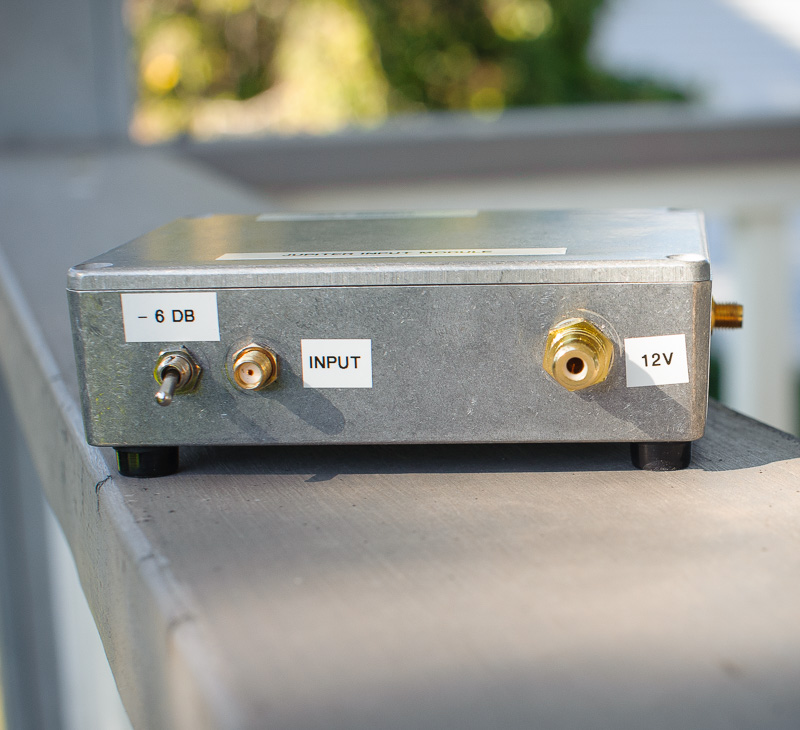
Above — Build of the input and RF preamplifier stage. I put in a 0 or 6 dB attenuator right at the input. That’s double-sided Cu+ board with copper vias joining the 2 surfaces intermittently and also at crucial ground points.

Above —Schematic with some data.

Above — SA + TG sweep of just the input filter board [ low-pass FL, plus triple tuned band-pass FL ]. I ran powdered iron toroids [ T44-6 & T50-6 ] wound with 21 gauge wire. The trimmer caps were SMT parts with a measured Qul of 1500 @ 1 MHz.
Standard band-pass filters filter steeper and deeper in the high-pass skirt, so I added the input low-pass filter to bolster the low-pass transfer function. It worked.

Above — After breadboarding the preamp, I put a connector on the input and output and measured some parameters.
I ran a RFMD [ now Quorvo ] SiGe HBT MMIC Amplifier; a 5 GHz part with a decent OIP3 and that well behaves with respect to parasitic oscillations. Still, then, with such a high Ft, it’s suicide unless you adopt a good layout, bypass into UHF, run 2-sided copper clad with via wires near the ground terminals, etc.
With the 1 nF series input and output caps, I measured gain from 1.459 to 50 MHz in this sweep. The 1 nF caps decrease the gain at 20.1 MHz and also at the top end of the broadcast AM band. See the gain at 1459 KHz = only 7.59 dB. Some of these high Ft MMICs exhibit massive gain down low and this can trash IMD from AM BCB interference. With the 1 nF coupling caps and the front-end filters, I don’t have to worry about the 10 KW AM transmitter located only a few Km from here.

Above — Sweep of the MMIC from 64 – 640 MHz

Above — Sweep of the MMIC from 0.65 – 3 GHz. I could find no unwanted parasitics with bench testing. Satisfied, I hooked up the preamp to the filter and enclosure mounted it.

Above — Sweep of the whole RF filter amplifier from port to port after re-tuning. Happily, the Hammond enclosure didn’t add any cavity effects to trigger unwanted oscillations.
I added the 3 dB output pad to further throw away some gain and ensure a wide band output into the mixer of the main receiver. Final S21 = 9.56 dB. The output 3 dB pad = 294.1 Ω 1% tolerance size 0805 resistors from a reel sent to me free by a kind reader + an 18 Ω 5% tolerance resistor I hand picked after measuring 17.7 Ω. The input switch attenuates the signal by 6.2 dB measured.
My goal was 10 dB gain with a stable, wide band match on the input and output. I did not go with the common gate JFET as it’s difficult to get a decent output return loss ( > 20 dB ) across a wide bandwidth into 50 Ω; plus I wanted a better OIP3. Still, too, the JFET proves a good low current choice for a Jupiter receiver preamp and its output Z is well suited for easily matching a NE612 Gilbert cell mixer input Z. I also purposely avoided a choke on the MMIC to keep the gain under ~10 dB.

Above — Return loss sweeps of the output port of the RF preamp/filter. Outstanding S22 over a wide band.

Above — Another photo of the entire stage. Built with Ugly Construction, plus hand carved pads of the correct width [ 50 Ω impedance] for the MMIC.