
PWM outputs’ test
Let’s deal now with the verification of the outputs for the motors command, if they are properly functioning: let’s activate the outputs by bringing the left stick down and on the right, the outputs will be brought from a value of 1,000 to 1,150 and the STATUS LED will turn on, so to indicate that the quadcopter is armed. At a later stage we will have to be sure that with a signal equal to 1,000 our motors won’t run, and that with a value of 1,150 they will idly run. Please inclinate the board to the right and verify that the right signal will increase, while the left one decreases. By inclinating the board upwards it will be the front signal to decrease and the rear signal to increase; this is the effect of the stabilization induced by the accelerometer (with the ANGLE mode activated). if you activate the MAG mode you will verify the stabilization on the YAW axis: if you try to rotate the board (while saying on the plane) you will see that the DX-SX signals and the FRONT-REAR signals will compensate the movement.
Mechanical parts assembly
With the command board tested and operational, it is possible for us to finally deal with the mechanics. The quadcopter’s frame must be assembled, according to the instructions included in the package; it is important that the assembly is an accurate and exact one, please tighten carefully each screw.
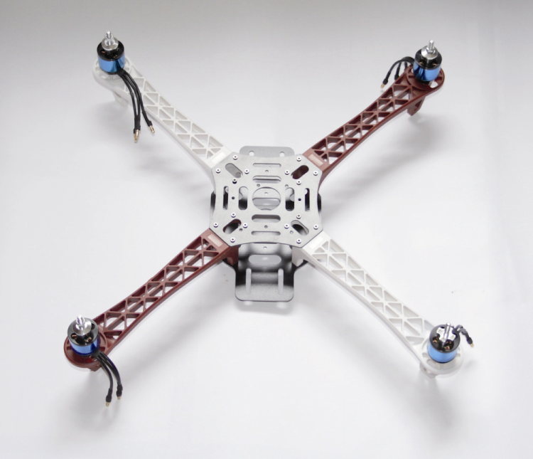
Afterwards, please block the motors with the specific screws and the related ESCs, by means of some small strips, in the inferior part of the frame’s arms, as shown in figure.

Please use the Power Distribution Board in order to connect the power source of all the ESCs to the battery cable; it is a board that is composed of tracks only, for the purpose of the distribution of the power on the side pads. Please don’t forget the small jumper that will bring the battery’s positive signal to the board for the purpose of measuring the charge level.
Above everything, please fix the control board, and preferably use plastic screws, for the purpose of avoiding both accidental short circuits and interferences with the IMU module; we will remember, in fact, that the magnetometer is sensitive to the presence of metal.

On completion of the work, the quadcopter – comprehensive of the battery having the expected capacity – weighs around 950 grams: a weight that is definitely inferior to the one that the four motors with the related propellers are capable of lifting. This allows us to take advantage of this loading “reserve” and mount a small video camera on board, with which to carry out some aerial shootings.


