
It’s time to follow up on the MPPT Solar Charger project. Progress has been slow since I’m currently working full time and doing a master’s degree at the same time. Given that this blog has previously been something close to a 50% job at times things will necessarily slow down a bit. But all the projects, including this one and the ultrasonic anemometer are alive and well and I’m working on them whenever I find some time.
User Interface
So what’s new with the MPPT solar charger? First of all, it got this nice user interface. Unfortunately there were still some issues with the first version so there is an identically looking but much-improved and bug-free Rev B. I’ll do a separate post on that documenting all the things I’ve changed.
I re-used the white-on-blue display from the initial version for the Rev B. as opposed to the black-on-white used with the Rev A. They are pin compatible so you can use whichever you prefer. I more and more start liking that black-on-white look. It’s about 10 bucks cheaper as well. What’s your opinion on this?

Solar Panel drains Battery
My intention with this design was to just leave the solar panel connected to the input of the buck converter. There’s a problem with that, however. The input of a buck is always at least at the output voltage minus a diode drop. With a 12V lead-acid battery at the output the input (i.e. where the solar panel is connected) the voltage never drops much below 12 volts.
That’s a serious problem since even a small solar panel like the monocrystalline 30W panel I have here sinks around 10mA at that voltage. So whenever the panel is not providing any power it considerably drains the battery.
Try a Diode
Obviously we need a way to avoid that. The first solution that comes to mind is a diode. But there’s a problem with that, too. To keep the power loss in the diode acceptable, the diode needs to have a low forward voltage. However, any diode with a low forward voltage also comes with a high reverse leakage. Physics seems to dictate that.
Leakage can easily be in the range of milliamps for a diode that can handle, say, 4A like needed here. And that reverse leakage is also highly temperature dependent. It may be ok-ish at room temperature and then detoriate by an order of magnitude at 50 degrees centigrade.
To get an acceptable reverse leakage one needs to tolerate at least half a volt of forward drop which is something like 3% in efficiency. Since our converter operates at around 97% efficiency that would mean doubling the energy dissipated.
P-Channel or N-Channel Mosfet
So the next obvious thing to try is a mosfet acting as a switch. Yes, a mosfet also has a body diode that also has a reverse leakage. But the body diode is a bad diode in terms of forward drop and has a correspondingly low reverse leakage.
A nice way of solving our problem would be to use a p-channel high-side switch disconnecting the battery from the converter whenever the panel is not producing. That not only disconnects the panel but powers off the entire buck including the input and output caps and everything. Where there is no voltage no power can get wasted. Perfect.

Unfortunately, powerful (i.e. low Rds-on) p-fets are relatively large, rare and expensive. As a rule of thumb a p-fet needs twice as much silicon area for the same performance compared to a n-fet. Besides that, that would be another type of component and I’m trying to not use too many distinct components.
So the other solution is to use an n-fet as low-side switch just disconnecting the panel. We already have 6 powerful n-fets in our design and they are cheap, too. So this is what I’ll do in the next version.
For now I’ve used one of the power outputs to connect the panel. I’ve cut some traces and soldered in some wires so that the fet is on whenever the buck is powered on.
Buck Software
During early testing of the buck converter I managed to kill the bottom fet several times. Since I was able to run the buck at relatively high power levels for prolonged periods of time without any issues (and without getting hot) I suspected that this was caused by carelessly written software. This seems to have been the case indeed. Whenever I killed a fet it happened at startup or shutdown, usually the latter. In the mean time I’ve written well-defined startup and shutdown routines and never had any issue since.
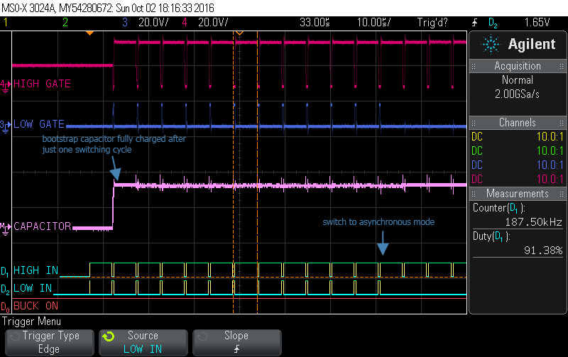
Synchronous converters are dangerous in this respect. It is very easy to short the battery to ground via the bottom fet. All it takes is a duty cycle that’s too low or a timer is running too slow or not at all. Or you stop the PWM module at a time when the bottom fet is on and it will stay on forever. Or at least a few milliseconds until it’s dead.
Asynchronous topologies are much more forgiving in this respect since you can’t short anything. So an easy solution would be to start up and shut down in asynchronous mode. We can easily make this an asynchronous converter in software by just not utilizing the bottom fet. The diode in parallel with it will then automatically take over.
Unfortunately we cannot start up in asynchronous mode. Why? To enable the upper fet we need a bootstrap voltage above the input voltage. And we don’t have that unless the converter is running. It’s a chicken and egg problem, really. So we need to start up in synchronous mode at least for a few switching cycles for the bootstrap diode to charge up.
That’s exactly what the startup routine does. It completes 16 cycles in synchronous mode at a neutral duty cycle. What do I mean by neutral? Simple: Duty Cycle = Output Voltage / Input Voltage. That means no current actually flows on average. So this is a nice, soft way to start up. After those 16 duty cycles the buck enters asynchronous mode. As the screenshot above shows, the bootstrap capacitor is fully charged after just one full duty cycle so that number is more than sufficient.
This routine is critical. If it doesn’t do precisely what it should chances are high that the buck is destroyed. So I’ve checked it carefully by both looking at the code and the scope. I’ve run it many times and observed closely what it does just to be sure it starts up nicely very time.
Why run in asynchronous mode? Because it’s more efficient at low power levels. Once the current rises above a software-defined threshold the converter will change to synchronous mode. If the current later falls below a second (lower) threshold, the buck changes back into async mode.
The optimal values for the two threshold will have to be determined experimentally but will likely be in the range of a few hundred milliamps.

The shutdown sequence is simple. The buck is shut down if the current falls below a very low threshold (say, 10mA) below which it cannot run profitably. If the current falls even lower we are better off shutting down the buck and entering a low-power mode. Since the current is low when we shut it off, the converter is already in async mode. So shutting it down is now easy and uncritical. We just turn off the top fet and can then also turn off the timer and supply voltage to the buck. The screenshot above shows an example of that.
Conserving power
A main feature of this solar charger is it’s ability to (hopefully…) run at a very low (<100microamps) current when not in use. So we obviously need to turn off everything we don’t need and run the PIC at a much lower frequency as well.
The PIC’s maximum operating frequency is 48MHz. This is the frequency it runs at when the buck and/or USB (not yet implemented) is on. These two features need that clock frequency to perform their task.
If both the buck and USB are off we can clock the PIC down to 8MHz which already saves a great deal of power. At 8MHz we can still do everything else, including running the user interface. Updating the display and particularly calculating the display content consumes quite some computation time and so we need a few MHz to do this.
If the user interface is not used for a certain time (say, 10 seconds), it is turned off. We can then lower the board voltage to 2.3 volts and lower the CPU frequency even further to 32.768kHz. This is the frequency of the real-time clock that is running anyway. At such a low frequency the PIC’s computational power is low but still sufficient to do some housekeeping tasks.
One can wake up the user interface at any time by pressing the push button. Turning the encoder won’t help because that, too, has been powered off.
While in this low power mode every 6 seconds the board voltage is raised to 3.3 volts and all temperatures as well as the input and output voltages are measured. That all happens at 32.768kHz. After the measurement is complete the PIC decides if the panel voltage is high enough to start harvesting energy or not. If this is not the case the board voltage is lowered again and a new set of measurements is captured 6 seconds later.

Despite all those efforts the board consumes something like 530 microamps which is much more than it should. About 100 microamps comes from the voltage divider used to measure the panel voltge. That’s an easy to solve design problem that I’ve described earlier already. But that still means that something is drawing 400 microamps. Not much at all but still way too much.
I’ve spent an evening trying to find the problem but I still don’t know. I’ve suspected the capacitors but when I measured some spare caps of the same type they hardly drew any current at 12 volts. I also un-soldered the buck’s mosfet driver but that made hardly any difference so that’s also not the problem. It may even just be some near-short on my board homemade board. So I leave that for now and check again once I have a revised design with a proper PCB.
Buck testing
I’ve saved the most interesting part for last  I’ve established before that this converter has a similarly high efficiency than the Arduino version published some time ago. But at that time I was only able to test up to 35 or so watts.
This solar charger is capable of handling much more power than that. Testing how much was a bit more difficult than expected. Unless the battery is very empty it won’t draw as much as this charger is able to provide. And you don’t want to discharge a lead acid battery too much, they don’t appreciate it at all. So once again my constant current dummy load came to the rescue.

With the dummy load at one of the power outputs I was able to draw some serious current. I set the dummy load to 4 amps and the battery absorbed (or provided) whatever was left. Obviously, I can only do that for a limited amount of time until the dummy load gets too hot. It automatically shuts down once the heat sink reaches 70 degrees centigrade which is soon the case at 4 amps.
I let the charger draw 4.5 amps at a bit more than 17 volts for as long as I could. The coil got quite warm, slightly hot even, maybe something like 60 degrees. The mosfet only got lukewarm and I’m not sure if this was because of their own power dissipation or due to their proximity to the coil.

So from this test I’d conclude that this was about the power which the charger can handle for a prolonged period of time. So I think something like 75 watts is a realistic power rating.
I’ve also had another look at the datasheet of the coil and it pretty much confirmed my findings. 75 watts at (say) 13 volts output corresponds to 5.8 amps through the coil. The datasheet states that the coil starts saturating at 8.2 amps which means we’re still safe with 5.8 amps plus the ripple current. The datasheet also states a 40 degree temperature rise at 5.3 amps. So thermally the coil is pretty much at its limit at 75 watts. That, too, seems realistic to me having touched it after some time at that power.
The road ahead
So how to continue? As we have seen, there is a number of design issues but the general concept works. During testing and debugging I’ve cut and re-soldered many traces and also made some modifications like the one with the n-fet described above. I’ve unsoldered and changed many components as well. All of that doesn’t improve the reliability of the board. At some point it makes sense to design a new version, build it and take it from there. A clean slate kind of.
I think this point has been reached here. So I will work on a new revision from now on. The concept won’t change at all but I’ll try to apply what I’ve learned so far. I also hope to reduce the number of different components, reduce the size and total cost while not sacrificing performance. In other words move a step towards a design that may one day be built as a small series. Let’s see.


