
Introduction
This little project will demonstrate how you can build NEC protocol based Infrared Remote Control to use with various NEC Protocol IR receivers.
actually there are lots of projects out there to accomplish this task but i have to write my own code because of too many requests on this IR(infrared) Remote Control Relay Board with PIC 12F675 Microcontroller people keep asking “Where is the Transmitter for this” although you can use any NEC protocol based remote ,but i just wanted to build one by my self. so here it is.
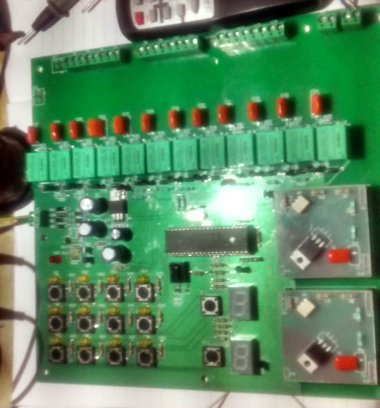
you can use this NEC IR Remote Control with my IR(infrared) Remote Control Relay Board .

12 Channel Relay + 2 Channel Dimmer control by IR Remote and keyboard
Consumer IR protocols
There are a number of consumer Infrared protocols out there and they have been used for every single purpose possible i guess, like PDA laptops and other consumer appliances. RC-5 & RC-6 by Phillips , RCA are few examples of consumer IR protocols.
There are a number of consumer Infrared protocols out there and they have been used for every single purpose possible i guess, like PDA laptops and other consumer appliances. RC-5 & RC-6 by Phillips , RCA are few examples of consumer IR protocols.
In this demonstration we will stick the to NEC protocol by NEC corporation,
NEC Infrared Protocol
- A 9ms leading pulse burst (16 times the pulse burst length used for a logical data bit)
- A 4.5ms space
- The 8-bit address for the receiving device
- The 8-bit logical inverse of the address
- The 8-bit command
- The 8-bit logical inverse of the command
- Final 562.5µs pulse burst to show end of message transmission.
- Logical ‘0’ – a 562.5µs pulse burst followed by a 562.5µs space, with a total transmit time of 1.125ms
- Logical ‘1’ – a 562.5µs pulse burst followed by a 1.6875ms space, with a total transmit time of 2.25
The transmission of 0 and 1 is shown in the image blow

There are four bytes of data bits are being sent in least significant bit first order the figure blow shows the format of an NEC IR transmission frame, for a command of 0xB1 (10110001b) and an address of 0x8D (10001101b) .
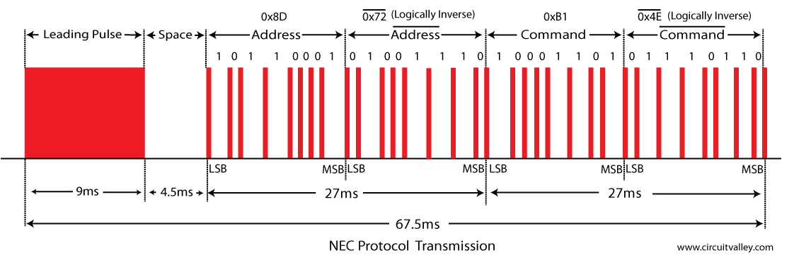
16 bits for the address (address + inverse) require 27ms to transmit time .and the 16 bits for the command (command + inverse) also require 27ms to transmit time.
because (address + address inverse) or (command+command inverse) will always contain 8 ‘0’s and 8 ‘1’s so (8 * 1.125ms) + (8 * 2.25ms) == 27 ms .
according to this total time required to transmit the frame is (9ms +4.5ms +27ms+27ms) = 67.5 ms.
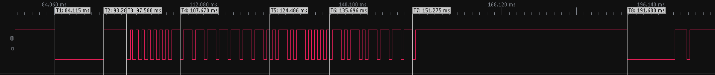
Verify with Oscilloscope and logic analyser
the image give blow is take by Rigol DS1052E Oscilloscope 

Logic Analyser shows the timing details
T1 leading pulse at 84.115ms
T2 space on 93.28ms
T3 Address starts at 97.580ms
T4 Address ends , address inverse starts 107.670ms
T5 address inverse ends , command starts at 124.486ms
T6 Command ends, command inverse starts 135.696ms
T7 Command inverse ends and last 562.5µs pulse to show end of transmission

Extended NEC protocol (not used in this demonstration)
The NEC protocol is so widely used that soon all possible addresses were used up. By sacrificing the address redundancy the address range was extended from 256 possible values to approximately 65000 different values. This way the address range was extended from 8 bits to 16 bits without changing any other property of the protocol. The command redundancy is still preserved. Therefore each address can still handle 256 different commands.in extended protocol instead of sending address and address inverse we send address low and address high as shown in the image blow.

Repeat Codes
If the key on the remote controller is kept depressed, a repeat code will be issued, typically around 40ms after the pulse burst that signified the end of the message. A repeat code will continue to be sent out at 108ms intervals, until the key is finally released. The repeat code consists of the following, in order:
A 9ms leading pulse burst
A 2.25ms space
A 562.5µs pulse burst to mark the end of the space (and hence end of the transmitted repeat code).
the figures give blow show the timing of repeat codes
.jpg)
if user keeps the key depressed the repeat codes keep coming
.jpg)
T8 shows the timing of repeat code
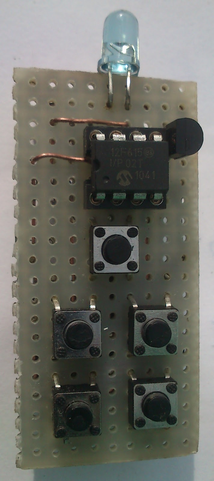
Encoding NEC Protocol with microcontroller
Schematic
As shown in the schematic and the pcb images this circuit use PIC12F615 as infrared encoder , the IR LED is driven by a separate npn transistor for longer range and the Coin cell Battery CR2032 is used to power the whole infrared remote. battery nominal voltage is 3.0V volts but as the datasheet says the PIC12F615 can work down to 2.0V.
for GP4,GP5,GP1,GP0 internal pullups are being used but the GP3 pullup can’t be used for GIPO as its is internally connected to MCLRE .
The current Consumption of the Circuit in sleep mode is around 35nA which is less then what datasheet claims. the CR2032 coin cell battery will last quite some time.

Hardware
.jpg) |
.jpg) |
Source Code
the Software utilize the internal PWM capability of the PIC12F615 to generate quite stable and accurate carrier frequency of 38Khz. most of the time Micro stay in the sleep mode ,even Brown out is enabled only when the wake mode to save battery. the current consumption is around 35nA when sleeping.
GitHub Repo.


