
I previously showed you my PIC32 proto board I made on verroboard (http://tahmidmc.blogspot.com/2014/02/pic32-development-proto-board-on.html). To make the proto board “more of a product” and easy to reproduce, I was working to make the proto board on a PCB.
I used ExpressSCH to draw the schematic, and used ExpressPCB to design the PCB. Once designed, Professor Bruce Land got the PCB made from ExpressPCB themselves.
The PCB is just to be a basic board with the PIC32MX250F128B placed on it. The power supply connections are provided as are external oscillator connections (if needed). Additionally, there is a nice convenient power supply input connector (standard 2.5mm jack/plug). All the IO pins along with power (Vin and +3.3V) and ground are placed on a SIL connector at the edge of the board so that the board can be conveniently placed on a breadboard for experimenting and prototyping (see pictures below).
It’s a nice little 2-layer PCB measuring only 3.1 inches by 1.8 inches. I chose to use all through-hole components to make soldering and construction easy for everyone. Now let’s look at the schematic, PCB mechanical view and some pictures of the actual PCB itself.
Here is the schematic:
Fig. 1 – Schematic (Click on image to expand/zoom)
Here is a mechanical diagram of the PCB:
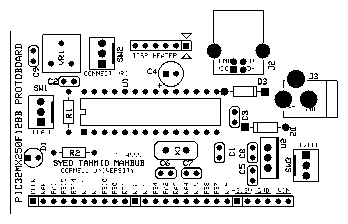
Fig. 2 – Mechanical diagram of PIC32 proto board PCB
You can find the ExpressSCH and ExpressPCB schematic and PCB design files at the end of this article.
There are some key things to note here.
- Use a ua78M33C or similar regulator for wide range voltage. Use an LDO voltage regulator if there is intention to power off of USB. Be careful about the LDO maximum input voltage rating. Currently, as it stands, the USB is not going to power the microcontroller (at least not reliably) due to the dropout voltage of the ua78M33C regulator. A regulator that can be used in its place so that the board can be powered either off of an external supply or the USB is the MIC2940A-3.3. Here’s the datasheet if you’re interested: http://www.micrel.com/_PDF/mic2940.pdf
- I used the 0.4in spacing PDIP28 component in ExpressPCB. I used a socket that allowed for that. But you may want to change it to a 0.3in spacing PDIP 28 package. It’s fine and working now. But I will change it in a later revision.
- C4 is VCAP. It is required for the stable operation of the PIC32MX250F128B. Use a low-ESR capacitor: defined by Microchip as having an ESR lower than 1Ω
- Mount X1, C6 and C7 onto the PCB only if there is a plan to use the external oscillator. Here the external oscillator is a standard crystal oscillator. If the internal oscillator is being used, don’t mount X1, C6 and C7 so that the associated IO pins can be used. Since the PIC32MX250F128B is only a 28-pin device, every single IO pin is valuable.
- Variable resistor VR1 is used to supply a variable voltage output to the PIC32MX250F128B pin 26, which is RB15 which is also AN9. This is just to provide a variable voltage to the PIC32MX250F128B for testing with ADC. There is a switch/jumper between the wiper of the variable resistor and the PIC32MX250F128B RB15. When the switch is not closed or the jumper is not shorted, the wiper is disconnected from the PIC32MX250F128B so that RB15 can be used for other purposes, eg external input voltage sensing, use as digital IO, etc.
- “Debug LED” is connected to RA0 (PORTA bit 0 –> pin 2) of the PIC32MX250F128B.
Here are some pictures of my PCB:

Fig. 3 – PCB just being mounted with components

Fig. 4 – PCB reverse side
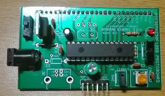
Fig. 5 – PCB top view (ignore the glare)
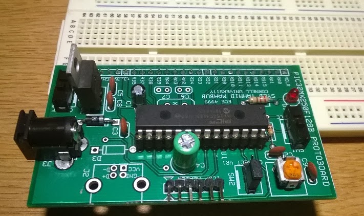
Fig. 6 – PCB placed onto breadboard

Fig. 7 – PCB placed onto breadboard – front view

Fig. 8 – PCB placed on table – you can see the IO pins

Fig. 9 – PICKIT3 connected to PCB
Here are links to the .sch ExpressSCH schematic file:
https://drive.google.com/file/d/0B4SoPFPRNziHU3pKMFFWSEdWOGs/edit?usp=sharing
https://drive.google.com/file/d/0B4SoPFPRNziHU3pKMFFWSEdWOGs/edit?usp=sharing
Here are links to the .pcb ExpressPCB PCB file:
https://drive.google.com/file/d/0B4SoPFPRNziHMWQtbVFHWU1JMXM/edit?usp=sharing
http://www.4shared.com/file/SdMQQzTyce/v1_i6.html
https://drive.google.com/file/d/0B4SoPFPRNziHMWQtbVFHWU1JMXM/edit?usp=sharing
http://www.4shared.com/file/SdMQQzTyce/v1_i6.html
You need the ExpressPCB software package to view and edit the .sch and .pcb files. You can get it from here: http://www.expresspcb.com/ExpressPCBHtm/Download.htm
Let me know what you think and I’d love to see what you do with this board. I’ve done quite a few projects with my verroboard proto board and I’ll be doing a series of small projects with this board. I’ll post them here from time to time.


