
Make it
Let’s move on now to talk about the machine’s construction. Its basic structure is made with square (27,5×27,5 mm) and angle (29,5×53,6×2,4 mm) aluminium extrusions, and by following the drawing in these pages. The actual chassis consists in two 27,5×27,5 mm extrusions, each one being 1 meter long. They are joined by a frame for each side, made with the same extrusions, but with different dimensions, that is, with a basis of 150 mm and a height of 330mm. Actually, the extrusions on the rear of the frames are 600 mm high. The assembly of the parts is made by means of screws, by closing each ending with the appropriate 27,5×27,5 mm caps.
In the front of the machine’s raised part, bottle supporting brackets have to be attached, by means of screws, at a distance of 97,7 mm from each other. At their bases, the dispensers have to be fixed, by means of appropriate screws; the leftmost bracket has to be exactly at 60 mm from the internal side of the upright, built from the square section (27,5×27,5×600 mm) extrusion.
The cart is a 3 mm thick, 192×100 mm aluminium slab, that has been conveniently worked by means of a CNC milling machine. A plexiglass slab of the same size is applied to it, worked so to be screwed in the underlying aluminium slab, and to host a small mug holder plate and possibly a LED ring.

The ring of LEDs is applied in the hole on the plexiglass of the carriage.
In the inferior part of the cart, on the short sides, two ball-casters with a 10 mm sphere are needed to make the cart slide along the cavities of the 1 meter long extrusions. The ball-casters have to be placed at a certain distance from the edges of the aluminium slab, so that they may slide within the cavities. The cart’s movement is achieved by fixing the belt around the pulley (on the right side) and to the stepper-motor. The same support, in addition to stopping the belt with a screw, is needed to move the lever of the limit switch. The position will be chosen, considering that the switch has to be pressed when the cart is fully placed at the beginning.
As it can be seen from the pictures, the switch has to be fixed, by means of one of the screws, with which the stepper-motor is stopped.
To avoid that fluids are poured when the cart is raised, to the 1 meter long aluminium extrusions two angle (29,5×53,6×2,4 mm) aluminium extrusions of the same length are applied. This is shown on the pictures in these pages, that is to say, with the corner on the outside.
As for the wiring, please follow the plan that has been printed on these pages: there you will find the connection of all the parts with the shield. As for the cart’s connections, please use some flat-cable whose conductors will have to pass three possible connections of the LED ring, in addition to the servo control’s connections. To avoid that the flat-cable gets entangled in the belt or that it hangs down, in our prototype we made it pass through a chain fairlead, as you can see from the prototype’s picture.
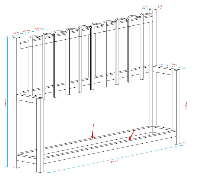
Machine frame: the 1-meter sections (arrows) must apply that limit the angular excursion of the carriage.
The electronics on board is composed by Raspberry Pi on which we applied the RandA board, that hosts the shield. We took into account that the whole would be placed in a 3D printed plastic container (with our 3Drag, if you have it at home…). Please place a small 12 V fan in it, for cooling purposes. If you apply the LED ring, please make the cable pass under the plate, by fixing it with appropriate clips, the same to be used to stop the LED strip on the angle extrusion in the rear. Once the various parts have been placed, you will have to apply the power supplies. Please remember that a 12 Vcc – 2,5 A power supply for the shield and a 5 V, 1,5 A one for RandA (that powers Raspberry Pi, by means of the inferior strips) are needed. The cables of the two power supplies have to be applied to the respective terminal box connections.


