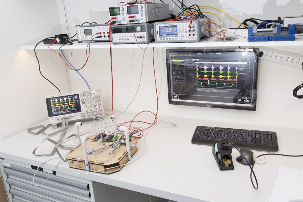
I last time proudly presented the new RevB board and got a lot of feedback from people who want one, too. As mentioned I have all the components here to ship up to 10 kits but I was reluctant to send anything until I had the chance to do some hardware testing. Not much had changed since the last revision but I don’t like taking chances on things like this.
In the mean time I managed to do some rudimentary testing and now feel confident to take orders. These tests concern the hardware only. What I said last time about the state of the software still applies. But let me tell you what I’ve been able to test so far.
Tests performed so far
- The PIC32 can be programmed from a PICKit3 via the ICSP header without any issues.
- Power consumption is as expected. Like the previous version it draws 45mA@12V (programmed) and the other two rails come up with +3.310 and -3.279V, respectively. Also as expected. Regulator stays cool.
- With the PIC controlling the AXIS, DIRECTION and SIGNAL pins, the transducers receive the 12V signal from the mosfet drivers. HOWEVER: the signals AXIS and DIRECTION are incorrectly labeled both in Eagle as well as on the silk screen. Electrically everything is fine but the names have been confused.
- The signal from the transducers is properly received (Rec pin on the board) and amplified by a factor of 11 by the first stage of the amplifier (S1 pin on the board).
- The PIC is able to control the digipot over the internal I2C bus and the second amplifier stage also performs as expected.
- The zero-crossing detector (ZCD) works.
- The input to the PIC’s ADC (ADC+ and ADC-) look fine, too. HOWEVER: the labeling on the silk screen is wrong. Eagle is correct, it’s just the silk screen. Plus should be minus and vice-versa. Again, electrically everything is fine.
- The PIC can communicate (as a slave) with an Arduino UNO connected to the external I2C bus.
- Communication over USB to a YAT-terminal under Win 7 works.
The following has not been tested so far
- For my tests I still used the transducers already used previously. I believe the ones I ordered last week are of the same type but I haven’t tested them.
- EEPROM. I haven’t tried the newly added memory yet. I have confirmed that it has power and is connected to the same bus as the digipot so I have no reasons to assume there are issues with it. But testing it would require some software first.
- The external SPI bus has never been tested, neither on the Rev A board nor with the new one. I don’t expect any problems but I haven’t done any testing so far.
Is there anything important that I forgot to mention? In that case just ask. A lot still needs to be done but at this point I’m confident that the board has no major flaws and performs much like the prototype. Want to give it a try? I have some kits left for you.


