
The WA2EBY amplifier is a famous linear amplifier project published in QST in March and April 1999 by Mike Kossor WA2EBY. As this amplifier can give up to 50W out with 1W drive, it is a perfect pair for my Softrock RXTX amplifier.
The articles can be found on the ARRL-site (search for WA2EBY) and are highly recommended reading.
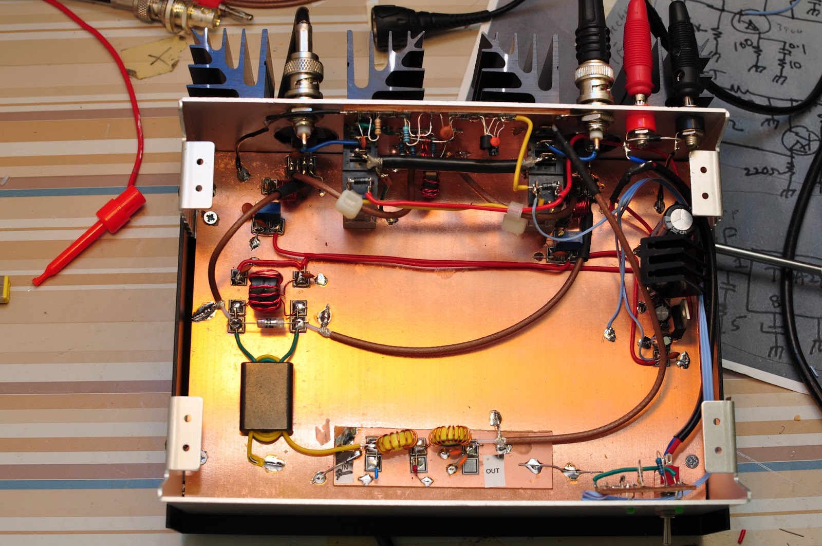
I have had a suitable box laying around for quite some time that was perfect for the amplifier project. I decided to go for Manhattan style construction using mainly the parts I already had in my junk-box and not order the PCBs and toroid set which are available from different sources on Ebay. In other words: a low-cost project.

The first I did was to make room for the IRF510 mosfets and two heat sinks. I drilled the holes in the aluminum box with a hole saw.
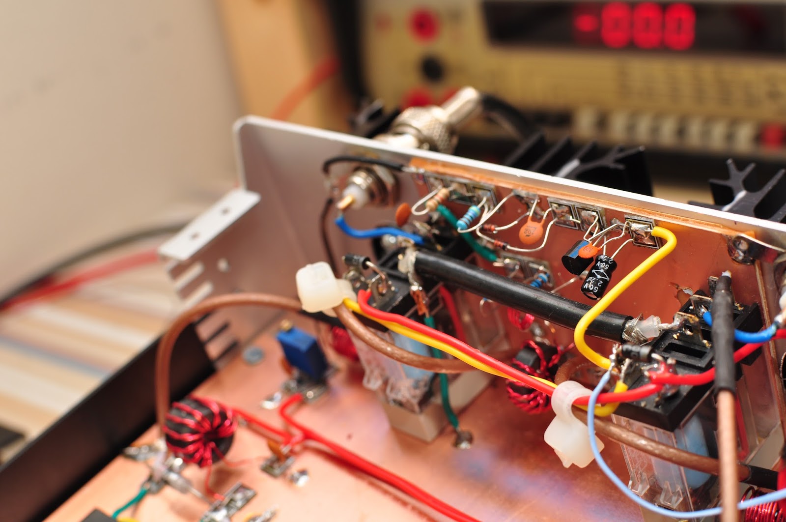
Then I made the RF-detector part (used for RX/TX) switching. It is in the upper part of the picture between the two relays.

I followed the articles and the schematics as best I could. The only alteration I did was to use 12V relays (instead of 15V) and a 7812 regulator for the relays and a 7805 regulator for the MOSFET bias instead of zener diodes. The above picture shows the power supply part. It is a rather conventional design. I addeda heat sink on the 7812 to make it handle 28V without dying on me.

I used a 1dB pad on the input (can be seen to the right of the left relay). It is probably not necessary to use a pad but it might improve the stability and provide a solid 50 Ω load for the Softrock RXTX Ensemble.

Mike Kossor recommends using teflon wire in output transformer due to the possible high temperature. I did not have that and used standard stranded wire which will probably survive just fine. I used coax cable for interconnections to and from the IRF510s.
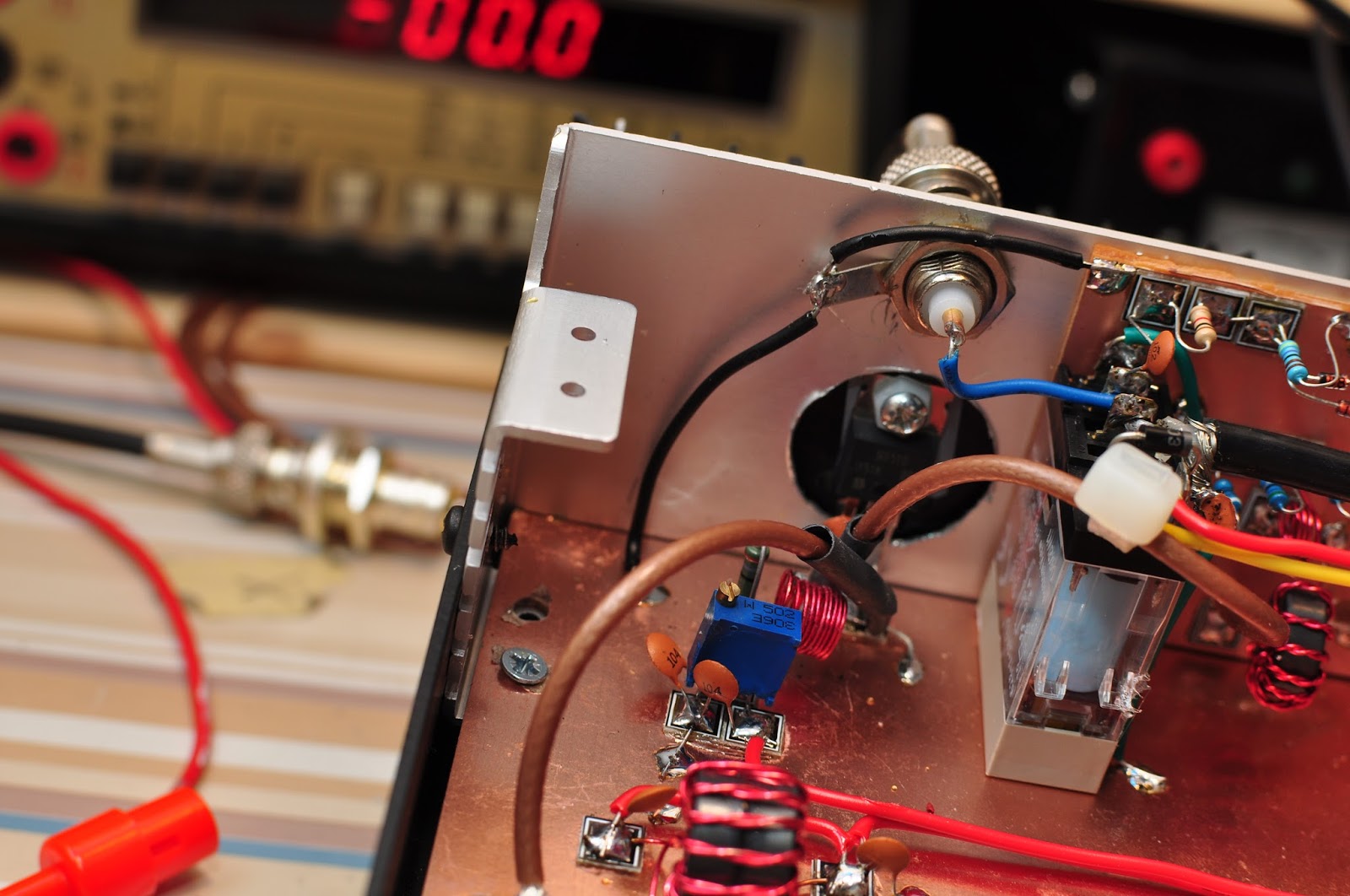
I used 5k potmeters for the bias adjustment. The value should not be critical since it only acts as a voltate divider. The article does not specify the bias current, and different sources on the Internet recommend between 10mA and 100mA. I decided to try 60mA and used the method described in W2AEWs excellent video.
I only made one of the many low pass filters in the schematic (for the 17m/20m bands) following the instructions from WA2EBY. There is no band-switching at the moment, but there should be plenty of room for that later.

The network analyzer plot shows that the filter is far from excellent. The -3dB point is as high as 20 MHz and the 2nd harmonic frequency for 20m transmissions is only about -23dB down. It does not mean that the filter is useless, but I will change it later to a steeper filter and lower the -3dB point when I`m at it. Nevertheless, the output waveform seems nice, and an FFT analysis show that the 2nd harmonic is within legal limits.
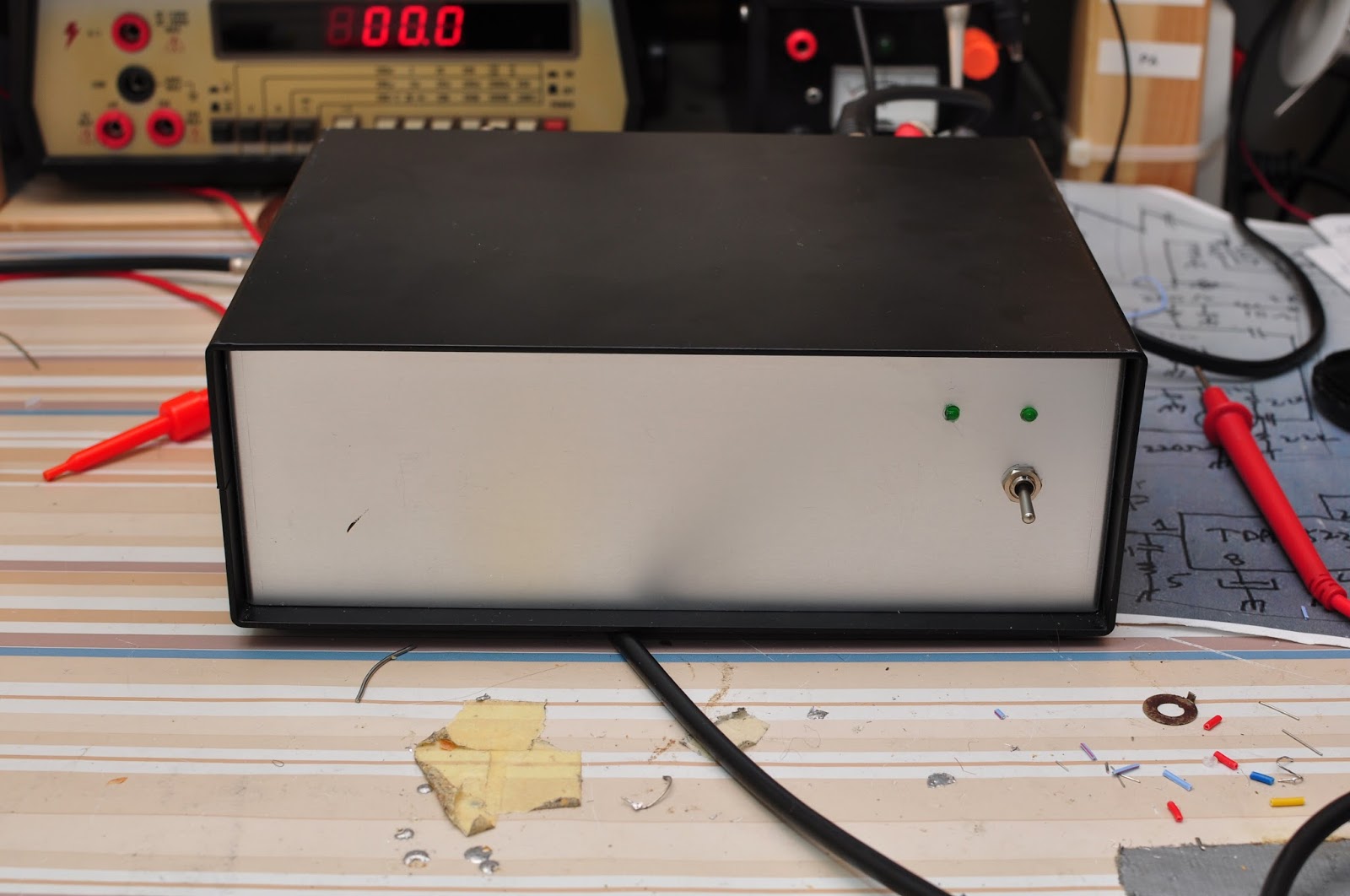
A picture of the final assembled amplifier. The switch on the front panel is on/off. One LED indicates ON, whereas the other indicates TX.

The rear of the amplifier. I used banana jacks since I like them, they are robust and cheap. A protective diode takes care of business should I ever connect red to black.
The verdict
Using a signal generator and a dummy load, the amplifier easily produces about 30 W on 1W input. The amplifier seems very stable, and I have had no problems what so ever. The power consumption and efficiency is about the same as WA2EBYs figures.
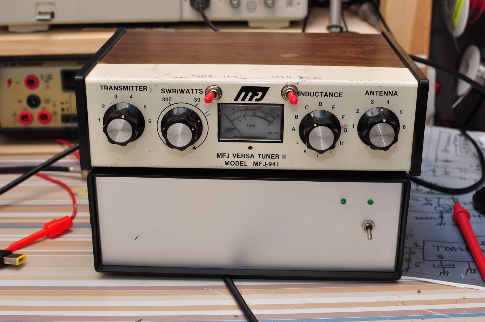
The above picture show the unit with an MFJ antenna tuner for size comparison. A nice pair. With my Softrock I usually drive the amplifier to about 10-15 Watts on 20V and this have given me many contacts on JT65/9. I live in an antenna restricted environment, and have struggled hard to get out with my mere 1W from the Softrock. I believe that this amplifier will give me lots of joy in the future.


