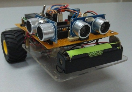
During my third year studying electronics engineering, I have made a wall following robot for the course EEE 351 Advanced Laboratory. This mini project is done in a team of four. For this project, we are required to apply control system theory into application, which lead us into making the wall following robot. As the name sounds, the robot’s main objective is to follow the wall within a target distance. In order to maintain certain distance from the wall, this is where we applied a digital controller, which is the PID controller. PID controller stands for Proportional, Integral and Derivative Controller which is used to calculate the error between the measured and desired set point and attempts to minimize the error. For more information about PID controller, have a look at Wiki.
Well, this is the group photo that we took after the project presentation. I would like to take this opportunity to thanks to my team members for all the support and help throughout the project. Besides that I would also like to thank to my lecturer for all the guidance given while working with this project. Without his guidance, we couldn’t achieve the goal of the project.
In this article , I will explain on how the robot works, the robot hardware and also the hardware implementation of this project.
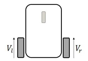
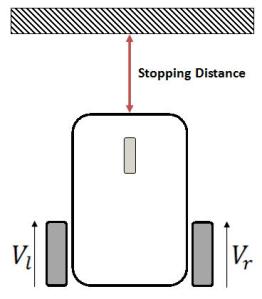
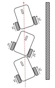
The main objective of this robot is to maintain a fixed distance from the side walls. Therefore, PID controller is used to adjust the speed of left and right wheels. The robot for this project is a differential drive robot where the robot movement is controlled by two separately driven motor.
There are three different ways to control the robot movement:
- Both left wheel and right wheel are moving at the same speed, . The robot is in forward linear movement.
- Both left wheel and right wheel are moving at the same speed, but opposite direction, . The robot will rotate at the midpoint of wheel axis.
- One wheel is moving while the other wheel is in stationary. The robot will rotate, with center of rotation at the stationary wheel.
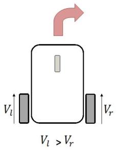
In this project, the speed of wheel is adjusted such that one wheel will be faster than the other one. The difference is speed of both wheels will vary the direction, of robot moving.
Basically, that is how to control the robot movement with the difference in speed for each wheels.
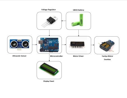
In this project, an Arduino Uno is used as the brain of the robot. It will be used to process the Ultrasonic sensor and perform PID controller which finally adjust the speed of both wheels.
Ultrasonic sensor is used to obtain feedback from the robot. The ultrasonic sensor will provide output where the width of the pulse is proportional to the distance measured. Therefore, Arduino is used to measure the pulse width and perform necessary calculations to convert it into distance in cm.
Tamiya Motor gearbox is used as the actuator which provides the movement for wall following robot. The gearbox consists of two independent motor which control the left and right wheel. The speed of motor can be varied with the voltage supplied to the motor.
To control the speed of motor, pulse width modulation (PWM) technique is used to vary the voltage of motor. Arduino is responsible to send the PWM signal to L293D Quadraple Half H Driver which control the voltage supplied to each motor.
This robot is powered with three 18650 batteries, rated at 3.7V each. Two of them are connected in series to create 7.4V which will pass to LM 7805 voltage regulator. The regulated 5V supply will power the Arduino Uno, Ultrasonic sensor and most of the electronic parts. Another 18650 battery is used directly to power up Tamiya Motor.
The closed loop system for the wall following robot is shown above. The input to the system is the target distance required for the robot to stay from the obstacle. An ultrasonic sensor is used to provide feedback from the robot position. The measured distance indicates how far the robot is from the obstacle. The error will be computed and processed through a speed of motor.
The working operation of wall following robot:
Basically the robot will keep on measure the front and side distance from obstacles. If there is any object blocking in front, the robot will stop moving until the obstacles is removed. When no object blocking the robot, Arduino will calculate the error between target distance and measured distance. The error value will pass to PID controller which will be used to control the speed of the left and right wheel.
As seen from the flowchart above, the main priority is first given to the front obstacle. The robot need to ensure that there is no obstacle in front to avoid collision. Only when there is no obstacle, the robot will consider moving in front while keeping the distance from side obstacle.
The method we used to fine tune the PID controller is by trial and error. Based on the understanding on each term, we tried to tune the PID controller to the least oscillation. We start off with pure Proportional (P) controller. It was found out that with pure P controller, the robot would overshoot if the gain is too high. For low gain value, there isn’t any noticeable effect on the robot.
Then we start to introduce the integral (I) and derivative (D) part into the controller. Integral helps the robot to reach the target distance by accumulate the sum of previous errors. Derivative helps the robot to reduce the overshoot compensating the overshoot made from integral part.
The final result of wall following robot is shown as figure below. Although there are still some oscillations at steady state, the percentage of overshoot would not cause big effect on the robot. Whenever there is a sudden change in measured distance, the PID controller will automatically corrects the robot position back to target distance.
Test for uneven surface 1
Test for uneven surface 2
Test for even surface
As you can see from the few videos above, the wall following robot able to follow the right walls quite accurately. Whenever there is a change in side distance, the robot will try itself to adjust accordingly to maintain the fixed distance from the side walls.
Final Robot demonstration
Initially, we can set the target distance desired to maintain from the side walls. When we are satisfied with the settings, triggering the start button will allow the robot operates.
Future work
This robot still has some limitations such as it can only follow the obstacle without a big change in angle. This is caused by the hardware limitations because it can only read angle perpendicular to the robot. When there is a big change in obstacle’s angle, it is unable to detect distance which will cause error to the robot. More ultrasonic sensor can be used on the robot to provide a wider field of view.
Currently the robot can only follow one side of the obstacle. To implement it as autonomous car, we need to make sure both side of robot is free from obstacle. Therefore, the solution is to have ultrasonic sensor on both sides of robot. So we can make sure the robot is always in the midpoint of two obstacles, thus prevent collision occurs.
Besides that, the robot will stop only when an obstacle in front comes into a preset distance. To further improve the robot, we can actually implement speed increment or decrement based on the obstacle in front. If there is no object in front it will accelerates whereas when object detected, the robot will decelerates according to the distance with front object.
Final thoughts
I have learnt a lot throughout the project especially the implementation of control system into hardware. We begin with an idea, lots of trial and error and finally we completed our project. It was great to have this opportunity to work on this project.
If you have any questions or suggestions, feel free to drop me a comment below.

