
Quick Answer
A connector is a joint designed to be taken apart. Its resistance comes from the few microscopic spots where the two surfaces really touch, so it is set by the contact force rather than by the size of the pins, and it degrades as the force does.
Intuition
The joint you have to be able to undo
A soldered joint is the ideal electrical connection. Two metals become one metal, the interface disappears, and nothing about it changes for decades.
A connector is the same joint with a requirement bolted on: it has to come apart, and go back together, and still work. Everything that is difficult about connectors follows from that one requirement, because a joint that can be separated is a joint whose two halves are only pressed against each other.
Press two pieces of metal together and they do not touch across the area you can see. Both surfaces are rough at a scale you cannot see, so they meet at a handful of high spots — a few micrometres across, sometimes fewer, against pins measured in millimetres. All the current has to squeeze through those spots.
That squeezing has a resistance of its own, and it dominates. It is why a connector's real specification is not a size or a plating or a current, but a force: how hard the two halves are pressed together, because that is what flattens the high spots and grows them.
And a force is a mechanical thing, so it decays. Springs relax, plastic creeps, plating wears through, a plug is inserted a thousand times, something is knocked. The resistance climbs, the joint heats, the heat accelerates the corrosion, and eventually somebody replaces a working circuit board because a connector had gone bad.
Practitioner
The spots you cannot see
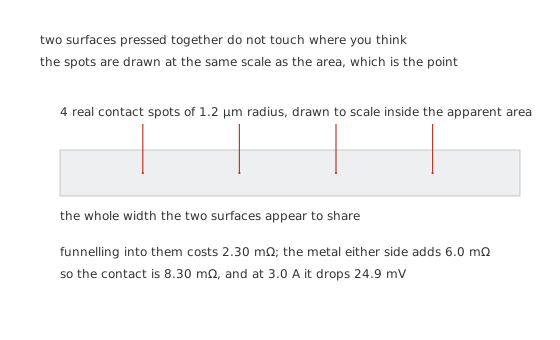
The spots are drawn at the same scale as the area, which is the point.
Worked example — Where a connector's resistance comes from
Take 4 real contact spots of 1.2 µm radius, in a metal of resistivity 22.1 nΩ·m.
Funnelling the current into a spot of radius a costs the resistivity divided by twice that radius. Four such spots in parallel come to 2.30 mΩ, and the bulk metal on either side adds an illustrative 6.0 mΩ.
The contact is 8.30 mΩ, so at 3.0 A it drops 24.9 mV and makes 74.7 mW.
The spot radius, the spot count and the bulk figure are invented illustrations. What is not invented is the shape of the dependence, and the next figure is why it matters.
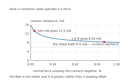
The floor is the metal, and it is physics rather than a drawing offset.
Worked example — What a loose connector costs
Press the contacts together harder and the high spots flatten, so their radius grows — with the square root of the force, on the standard elastic model.
At the rated 1.0 N the contact is 8.30 mΩ. At 100 mN, a tenth of it, the contact is 13.3 mΩ — 1.60 times as much, and 39.8 mV of drop instead of 24.9 mV.
The curve flattens onto 6.0 mΩ however hard you press, because that part is the metal rather than the interface.
A tenth of the force costs less than you might expect, and that is worth noticing too. The square-root dependence is gentle, which is why connectors mostly degrade slowly and then fail suddenly: the resistance climbs gently while the force decays, then the heat it makes accelerates the corrosion, and the corrosion is not gentle at all.
Engineer
Two ways the arithmetic surprises people
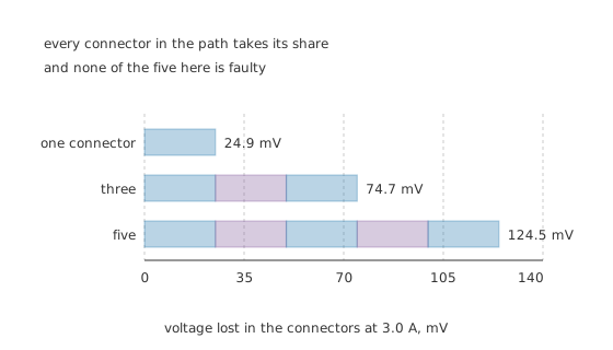
Every connector in the path takes its share, and none of the five here is faulty.
Worked example — A supply that arrives low for no reason
Trace a rail from a power supply to a board: a supply outlet, an inline plug, a chassis feed-through, a board header, a jumper. That is 5 contacts, and they are in series.
5 times 8.30 mΩ is 41.5 mΩ. At 3.0 A that is 125 mV lost and 374 mW of heat.
On a 5.0 V rail, 2.49 % has gone before the load sees anything, and every connector in the chain is doing exactly what it was specified to do.
The second surprise is about pins.
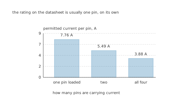
The rating on the datasheet is usually one pin, on its own.
Worked example — Why four pins do not carry four times as much
Each loaded pin makes heat, and all of them heat one housing. Against an illustrative 60 °C per watt and a permitted rise of 30 °C, solve the balance for the current.
One pin on its own may take 7.76 A. Two pins may take 5.49 A each. All four may take 3.88 A each.
That is a factor of 2.00 from one pin to four, and it is exactly two rather than approximately: the current enters the heat balance squared while the pin count enters it once, so the per-pin limit falls as one over the square root of how many are loaded.
Doubling up pins to carry more current works, and it works less well than it looks. Two pins in parallel share the current, but they also share a housing, so the pair carries about 1.41 times what one pin alone could — not twice. And they only share the current if their resistances match, which two contacts of a real connector do not.
Professional
Choosing, fitting and not being caught out
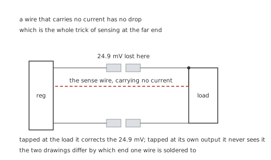
A wire that carries no current has no drop, which is the whole trick of sensing at the far end.
Where a voltage is regulated decides whether the connector drop matters at all. A sense wire carries almost nothing, so its own contact loses almost nothing, and a regulator that measures at the far end of the connector corrects for the 24.9 mV automatically. Measure at its own output instead and the drop is uncorrected. Those two circuits differ by which end one wire is soldered to.
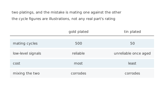
The mistake is mating one against the other.
Plating is a lifetime specification, not a quality grade. An illustrative gold contact survives 500 matings against a tin one's 50, and holds up in low-level signal paths where tin's oxide eventually does not. Tin is cheaper and entirely adequate for a connector mated once in a factory. What is never adequate is mating a gold contact against a tin one: the two form a galvanic pair, both corrode, and the joint fails faster than either would alone.
Strain relief is an electrical specification in disguise. Every newton pulling on a cable is a newton not pressing the contacts together, and the wire's own flex fatigues at the crimp. A connector without strain relief is a connector whose contact force is set by whatever the cable is doing today.
Crimp, do not solder, where a crimp is specified. A proper crimp is a gas-tight cold weld with no flux residue and no wicking; solder wicks up the strands, makes a stiff section just past the joint, and puts the flexing exactly where the wire has become brittle.
Keying and polarisation are worth paying for. A connector that can be inserted backwards eventually will be, and the failure is usually expensive. So is a connector identical to the one next to it carrying something different.
Mating under load is a different duty entirely. Contacts that mate with current already flowing arc as they part, exactly as a switch's do, and connectors intended for it have longer contacts on the pins that should make first and break last. Ordinary connectors do not, which is why unplugging a live supply damages both halves.
Contact geometry is a real choice, not a styling one. A round pin in a round socket touches on a line and depends entirely on the socket's spring; a fork or tuning-fork contact grips from two sides and holds its force better as it wears; a blade contact spreads the same force over a longer line and carries more current for it. Insulation-displacement contacts cut through a ribbon cable's insulation and form their gas-tight joint against the copper without stripping anything, which is why a ribbon cable can be terminated in one squeeze — and why re-terminating the same cable a centimetre further along is the correct repair rather than reusing the connector.
Board-to-board connections have a failure mode of their own. Two boards joined by headers are mechanically coupled, so anything that flexes one board works the other's contacts, and a connector chosen for its electrical rating can fail because nobody specified how the assembly is held together. A mezzanine connector's height tolerance and a board's own bow are in the same budget as its contact force.
Measure a suspect connector under load, not with a meter. A four-wire measurement or a voltage drop taken at the working current tells you what the contact is doing; an ohmmeter's test current is small enough to be blocked by a film that amps would punch through.
Common mistakes
- Thinking a bigger pin means a lower resistance — the resistance is set by the microscopic spots, and those are set by the contact force. Four spots of 1.2 µm radius here contribute 2.30 mΩ regardless of how big the pin looks.
- Ignoring the chain — five ordinary contacts at 8.30 mΩ each is 41.5 mΩ and 125 mV at 3.0 A, which is 2.49 % of a 5.0 V rail lost before the load sees anything.
- Adding up pin ratings — four loaded pins take 3.88 A each against a single pin's 7.76 A, a factor of exactly 2.00, because they all heat one housing.
- Mating gold against tin — the pair is galvanic, both corrode, and the joint fails sooner than either plating would alone.
- Sensing at the regulator rather than at the load — the connector's 24.9 mV goes uncorrected, and the two circuits look almost identical on a schematic.
- Testing a suspect contact with an ohmmeter — its test current is too small to break through a surface film that the working current would punch straight through.
Frequently asked questions
Why does a connector have resistance at all?
Because the two surfaces touch only at a few microscopic spots and all the current has to funnel through them. Four spots of 1.2 µm radius contribute 2.30 mΩ of constriction resistance here, and the metal either side adds 6.0 mΩ, for 8.30 mΩ in total.
Why is contact force the specification rather than contact area?
Because force is what creates the contact spots. Their radius grows with the square root of the force, so the resistance falls with it: this contact is 8.30 mΩ at 1.0 N and 13.3 mΩ at 100 mN, 1.60 times as much. Below the bulk metal's 6.0 mΩ no force can take it.
Can I use two pins to carry twice the current?
Not quite. Both pins heat the same housing, so with two loaded each may take 5.49 A against a single pin's 7.76 A — the pair carries about 1.41 times what one could. With all four loaded it is 3.88 A each, exactly half the single-pin figure.
Why did my 5 V rail arrive at 4.88 V?
Possibly because there are five connectors between the supply and the board. At 8.30 mΩ each that is 41.5 mΩ, which at 3.0 A loses 125 mV — 2.49 % of the rail — and dissipates 374 mW spread through the housings, with nothing faulty anywhere.
Is gold plating worth it?
For anything mated often or carrying low-level signals, yes: an illustrative 500 cycles against tin's 50, and no oxide to block a microamp. For a connector mated once in a factory, tin is fine. What is never fine is mating gold against tin, because the pair corrodes.