
Switched-mode power supplies
The switched-mode power supplies work according to a completely different principle; they transform the parameters of the power, by transferring it from the input to the output under the form of pulses, that are then applied to a capacitor on whose ends a voltage is obtained; the continuous value of the latter is equal to the mean value of the waveform built by the pulses. In comparison to linear regulators, they have two great advantages: they allow – if necessary – to obtain output voltages that are higher than the input ones and that guarantee a higher efficiency, independently from the input voltage; this last feature is due to the fact that the conversion of the voltage in pulses is obtained by means of transistors operating as static switches (and not as amplifiers) and that, therefore, even at high currents they dissipate a minimal power.
We are interested in a specific category (that is the most used one) of the switched-mode power supplies, that is to say the inductance load type; with a great degree of simplification, it “accumulates” a certain amount of energy – drawn from the input and released at the output – inside a coil, with a theoretical efficiency that is a bit under 100%.
In figure we may see a principle diagram of a switched-mode power supply, capable of reducing the input voltage (similarly to what the abovesaid linear regulator does); the switch in the picture is obviously substituted by a transistor (almost always a MOSFET), but the circuit may be ideally created even with mechanic components only, it being understood that the limits in the commutation speed are still valid.
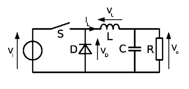
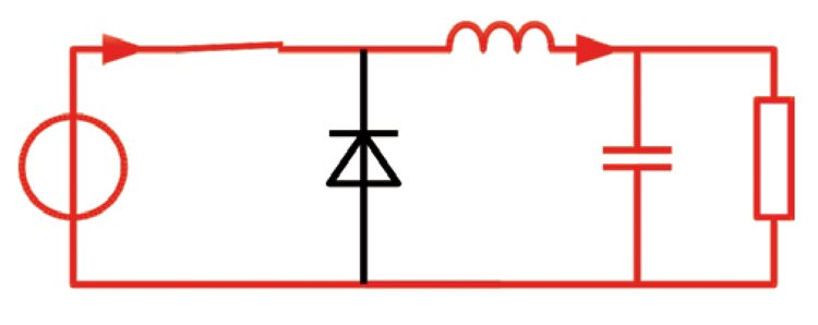
When the switch gets closed, the current does not pass through the diode (that turns out to be inversely polarized, having a positive voltage at the cathode) and goes to load the inductor; by opening the switch, the inductor tries to keep constant the current that flows through it, therefore the current flows through the diode and the load, as in the diagrams shown in figures. The two operating stages are therefore:
- closed switch; the current flows from the generator to the load, passing through the inductor that is therefore loaded; the diode turns out to be inversely polarized and therefore it does not conduct;
- open switch; the inductor is unloaded by means of the load and the diode, that in this case turns out to be directly polarized.
Let’s talk a bit about the theory regarding this type of converter, now, so to familiarise (within the limits of the article) with its functioning and terminology.
As a first thing we will start from the premise that the output voltage at a given moment is the required one, Vo, while the input one is Vi.
From the diagram, it is possible to infer that in that moment, the voltage at the inductor’s ends is equal to Vi-Vo with the switch closed, and equal to Vo (save for the Vd drop on the diode, that we will disregard for now) with the switch open.
Also, let’s imagine (and it’s a realistic hypothesis for loads that are not too low) that the current in the inductor never goes to zero, and therefore that the converter works in a continuous mode (CCM).
The topic of the discontinuous mode (that is to say, in the case the current in the inductor goes to zero) is much more complicated and we will therefore avoid it.


