
Increasing the input voltage
The switching converter seen until now is capable of decreasing the generator’s voltage, so to bring it to the one that is necessary for the load, that is to say it is capable of obtaining an output voltage that is lower than the input one; it is therefore named “step-down” converter.
What happens, however, if the need is the opposite one, that is to say if we have – for example – a LiPo battery capable of supplying a voltage ranging between about 3 and 4 volts, and we are in need of the fateful 5 volts?
In this case another type of switching converter may help us, it is named boost converter, that is to say it is a “step-up” converter.
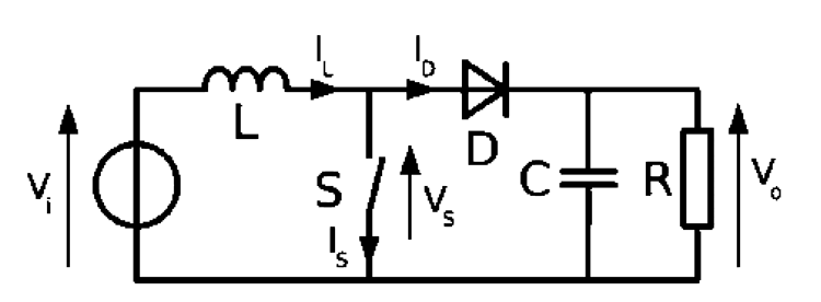
As it can be seen from figure , that schematises it, the difference with respect to the previous principle diagram is that the inductor is found before the switch and that the latter short-circuits it towards ground.
The two operating stages are:
- closed switch; the current flows from the generator (the voltage applied to the converter’s input) in the inductor, thus loading it;
- open switch; the inductor tries to keep the current flow of when the switch was closed, by reacting to the opening with an inverted extravoltage that finds an outlet in the capacitor and that flows in the same direction, and loading the capacity with a positive polarity on the diode’s cathode.

In summary, when the switch is closed all the current supplied from the generator goes to load the inductor, while the load is powered only by the output capacitor; while with the switch open, the inductor is in series with the generator and therefore the voltage to its ends is added to the one from the generator itself, thus increasing it. The diode is needed – in the stages in which the switch is closed and the inductor is being charged – in order to avoid that the capacitor is emptied by the switch itself.
Without having to repeat the previous calculations, and always under the same hypotheses, the equation used for the calculation of the output voltage becomes:
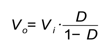
Since D is always less than 1 (the duty-cycle… Do you remember it?) the output voltage will always be greater than the input one.


