
Efficiency of the switching converter
When analyzing the ideal circuit we talked about until now, the first thing that stands out is that there are no resistive components in it: the energy supplied from the power source goes to load an ideal inductor (thus having a zero ohm resistance) which is then discharged on the load by means of the same and the diode, that is also imagined as an ideal one.
Therefore, all the energy drawn from the generator is transmitted to the load with a 100% efficiency.
A nice step change in comparison to the 60-40-20% of the linear regulator!
Unfortunately, ideal components do not exist: the inductor is composed of a copper wire with a certain resistance, the diode – even if accurately selected – has a certain voltage drop at its ends, the same PCB tracks are in copper and therefore affected by the electric resistance and the switch, that in the 99% of the cases is made of a MOSFET, and has an insertion resistance, albeit a minimal one. In fact, even if the technology of these components made enormous progress in the last decades, the MOSFET has an ohm resistance between drain and source and a switching time that are not null. This is translated in a loss of efficiency, whose calculation falls outside the purpose of this article, and it is verifiable by measuring the absorbed current and the one supplied at the load. The absorbed power is in fact equal to:
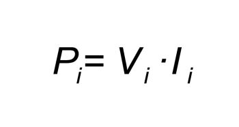
while the power returned to the load is equal to:

And the efficiency is given by:
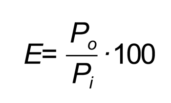
In the actual conditions of our converter, it is always true that Po < Pi and therefore there is an efficiency that is lower than the theoretical 100%. We will see the values in the field when talking about our actual circuit.
The ripple
Until now, we have seen how our converter takes advantage of the inductor for the purpose of storing energy that is then returned to the load at a different voltage, and this is done by means of a switching mechanism, and differently from the linear regulators we saw before.
It is therefore obvious that, among all the qualities of our converter, a great flaw appears: we may see a variable (more or less small) voltage, named ripple, overlapping the direct output voltage.
How small it is? It depends mainly from the value of the output capacity and from the switching frequency; the higher are the values of the said parameters and the lower the ripple will be, with the problems we saw until now, that is to say: encumbering capacity and other problems if we increase the capacitor, and switching problems/technological limitations if we increase the frequency.
Even the inductance and other parameters influence the ripple. We need therefore the usual compromise between values, and for such a reason it is necessary to calculate the ripple and to decide if it is an acceptable value or not.
Unfortunately, an accurate calculation of the ripple is quite a complicated one, and we will see that quite in detail in the final diagram; at the moment, it is sufficient to know that by increasing the capacity and/or the frequency, the ripple decreases.


