
Quick Answer
A quartz crystal is a mechanical resonator with electrical terminals. Its vibration behaves as an extremely high-Q series circuit, giving two resonances a fraction of a per cent apart. Ceramic resonators work the same way at a hundredth of the quality factor, with accuracy and cost to match.
Intuition
A lump of quartz that will not be hurried
Everything else in a circuit responds instantly, or near enough. Push a voltage at a capacitor and the charge moves at the speed electrons move. Put current through a coil and the field is there. Nothing in an ordinary circuit has any weight to it.
Quartz does. A crystal is a small slab of it with metal plated on two faces, and it works because quartz is piezoelectric: squeeze it and a voltage appears across the faces, apply a voltage and the slab deforms. So an electrical signal can make the slab move, and the moving slab makes an electrical signal in return.
A slab of anything, set moving, has a frequency it prefers — the one its own size and stiffness pick out. Quartz's preference is extraordinarily strong, because it is a nearly perfect elastic solid and almost nothing damps it. Set it ringing and it rings for a very long time.
That is the whole component. The circuit is not choosing the frequency at all. The circuit is providing a little energy each cycle to keep the slab moving, and the slab is telling the circuit when.
The practical consequence is a part with a mechanical property dressed as an electrical one: an equivalent inductance no coil could be wound to, a Q no arrangement of copper and iron could reach, and a frequency that depends on the physical dimensions of a piece of rock.
Practitioner
Four components that are really one slab
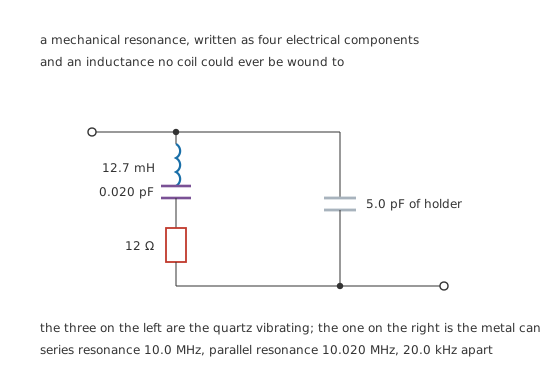
The three on the left are the quartz vibrating; the one on the right is the metal can.
The vibration behaves electrically as a series circuit — an inductance standing for the slab's mass, a capacitance for its stiffness, a resistance for the little energy it does lose. Across all three sits a real, ordinary capacitance: the two electrodes with quartz between them.
Worked example — An inductance nobody could wind
Take an illustrative motional capacitance of 0.020 pF and require the series arm to resonate at 10.0 MHz. Solving the resonance condition for the inductance gives 12.7 mH.
That is a real number in the sense that the circuit behaves as though it were there. It is not a coil, it is the mass of the quartz, and no winding of that inductance would fit in the can.
Put the motional resistance of 12 Ω against it and the quality factor is 66.3 k, which puts the whole resonance inside a bandwidth of 151 Hz.
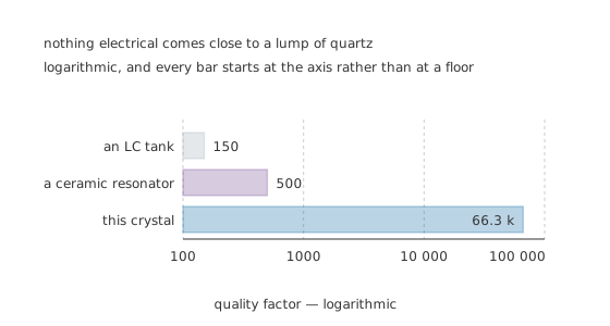
Logarithmic, and every bar starts at the axis rather than at a floor.
Against an illustrative LC tank at 150 that is 442 times sharper, and against a ceramic resonator at 500, 133 times. Nothing built from components reaches it.
Every figure in this lesson is an invented illustration. Motional parameters differ between cuts, frequencies and manufacturers, and a real datasheet gives them with tolerances.
The frequency on the can is the frequency of a mode, not of the slab. A crystal cut for tens of megahertz is thinner than is practical to make, so parts above about 30 MHz are usually run on an overtone — the third or the fifth — with the fundamental deliberately suppressed by the circuit around them. Order a 100 MHz crystal and you are ordering a slab whose fundamental is near 33 MHz, together with an instruction that the oscillator must not start there. Overtone parts and fundamental parts of the same nominal frequency are not interchangeable, and a circuit that ignores the distinction will happily oscillate at a third of the intended rate.
A tuning fork is the other geometry. The 32.768 kHz parts in every clock are not slabs at all but a two-pronged fork etched from quartz and flexed rather than sheared. That gives 32.768 kHz — three hundred times below this lesson's 10.0 MHz example — in a package small enough for a wristwatch, at the cost of a quality factor well short of a shear-mode part's 66.3 k and a temperature characteristic that is a parabola rather than a gentle cubic. The two are different components that happen to share a name.
What you can measure and what you cannot. A meter tells you nothing about a crystal — it is an open circuit at DC and a very small capacitance at any frequency a meter uses. The motional parameters need a network analyser or a purpose-built crystal impedance meter. In practice the test is whether the oscillator built around it starts, and at what frequency, which is why the next layer is about the circuit rather than the part.
Engineer
Two resonances, and only one narrow window between them
The holder capacitance across the motional arm is not a parasitic to be ignored. It creates a second resonance, and the gap between the two is the only frequency range an oscillator can use.
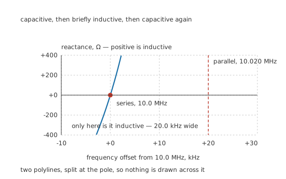
Capacitive, then briefly inductive, then capacitive again.
Worked example — Where the two resonances fall
The motional arm alone resonates at 10.0 MHz: below it the arm is capacitive, above it inductive, and at it the reactance is zero.
Above that point the arm's inductive reactance climbs until it cancels the holder's 5.0 pF, which is a second resonance — this time a parallel one, at 10.020 MHz.
The gap is 20.0 kHz, or 1998 parts per million. Between those two frequencies the crystal looks inductive to the circuit; everywhere else it looks capacitive, and an oscillator built round it will not start.
Two parts per thousand does not sound like a window worth naming. Against a Q of 66.3 k it is enormous — the resonance itself is only 151 Hz wide — and every crystal oscillator ever built works somewhere inside it.
Which end of the window a circuit lands on is a design choice with a name. A series-mode oscillator drives the crystal at the bottom of the window, where its impedance is a minimum and the crystal acts as a very selective short circuit. A parallel-mode oscillator works higher up, where the crystal is inductive, and it needs a specified load capacitance to land where intended. Most microcontroller oscillators are the second kind, which is why a datasheet's frequency is quoted with a load capacitance beside it.
Drive level is a real specification. The slab is being physically flexed, and flexing it too hard ages it and eventually cracks it.
An illustrative ceiling of 100 µW against 12 Ω allows 2.89 mA through the crystal, and an oscillator with too much gain and no series resistor exceeds that easily.
Professional
The capacitors round the crystal are part of the crystal
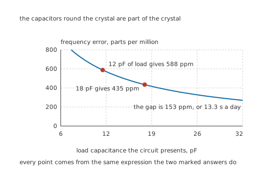
Every point comes from the same expression the two marked answers do.
A parallel-mode crystal is specified for a load capacitance, and the circuit has to present exactly that. It rarely does, because the load is the two capacitors you fitted plus the oscillator pins' own capacitance plus the track capacitance plus whatever the case is doing.
Worked example — Six picofarads and thirteen seconds a day
A crystal cut for 18 pF of load runs 435 parts per million above its series resonance.
Present it with 12 pF instead and it runs 588 parts per million above instead.
The difference is 153 parts per million, which over 86400 s is 13.3 s. It is also only 13.0 of the crystal's whole pulling range, so the oscillator starts, runs, and looks completely healthy while losing a quarter of a minute a fortnight.
That is the single most common crystal fault, and it never looks like a fault. The frequency is close, the circuit is stable, and nothing indicates a problem until something has to agree with something else.
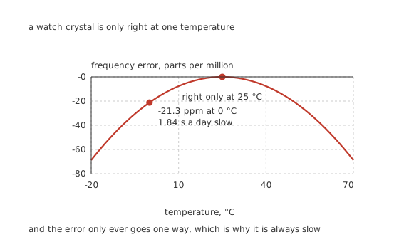
The error only ever goes one way, which is why it is always slow.
Worked example — Why the clock loses time in winter
A tuning-fork crystal — the kind in every watch and real-time clock, cut to divide neatly down to one pulse a second — has a temperature characteristic shaped like a downward parabola about a turnover temperature.
At an illustrative -0.034 parts per million per degree squared about 25 °C, being 0 °C instead costs -21.3 parts per million.
Over a day that is 1.84 s, and it is always in the same direction: a watch on a wrist keeps better time than the same watch in a drawer, and neither ever runs fast.
Choosing between them
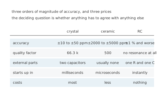
The deciding question is whether anything has to agree with anything else.
A ceramic resonator is the right answer more often than its reputation suggests. It is a piezoelectric ceramic rather than quartz, so the Q is a hundredth of a crystal's and the accuracy is measured in thousands of parts per million rather than tens. For a microcontroller that only has to sample a keypad and blink a light, that is fine, and the part usually integrates its own load capacitors and starts faster.
Anything that has to agree with something else needs quartz. Serial links, radio, and any clock a person will compare with another clock. The threshold is usually a few hundred parts per million, which a ceramic resonator cannot promise and a crystal beats without effort.
Layout matters more than it looks. The two load capacitors and their return path are inside the resonant loop. Long tracks add capacitance that shifts the frequency, add inductance that can start the crystal on an overtone instead of its fundamental, and pick up noise that ends up as jitter.
Ageing is real and it is one-directional. A crystal's frequency drifts over years as stress in the mounting relaxes and contamination settles on the slab. It is small — parts per million per year — and it is why a clock calibrated once is not calibrated forever.
Never test a crystal by putting a scope probe on it. The probe's capacitance is a substantial fraction of the load, so measuring the oscillator changes the thing being measured. Probe the buffered clock output, or use a probe with a tenth of the capacitance and accept that it is still an approximation.
Common mistakes
- Fitting the wrong load capacitors — 12 pF where 18 pF was specified moves this crystal from 435 to 588 parts per million, a 153 ppm error and 13.3 s a day, with no other symptom at all.
- Forgetting the strays — the load a crystal sees is the two capacitors plus the pin capacitance plus the track. The capacitors to fit are always smaller than the specified load, not equal to it.
- Confusing the two resonances — this crystal is 10.0 MHz in series mode and 10.020 MHz at parallel resonance, 20.0 kHz apart, and a circuit designed for one mode will not land where you meant in the other.
- Overdriving it — an illustrative 100 µW ceiling against 12 Ω of motional resistance allows 2.89 mA through the slab, and an oscillator with excess gain and no series resistor passes more.
- Expecting a ceramic resonator to hold a serial link — its quality factor is 500 against this crystal's 66.3 k, a factor of 133, and its accuracy is measured in thousands of parts per million.
- Probing the crystal pins — the probe becomes part of the load capacitance and shifts the frequency you are trying to measure.
Frequently asked questions
Why does a crystal have two resonant frequencies?
Because the vibrating quartz behaves as a series circuit and the electrodes add a real capacitance across it. The series arm resonates at 10.0 MHz here; a little higher, the arm's inductance cancels the 5.0 pF holder capacitance and the whole network resonates again at 10.020 MHz. The 20.0 kHz between them is the only band where a crystal looks inductive.
What load capacitance should I fit?
Whatever makes the total load equal the crystal's specified figure, which means the capacitors you solder down are smaller than that figure because the pins and tracks contribute too. Getting it wrong by 6 pF here moves the frequency 153 parts per million, or 13.3 seconds a day.
How can a crystal have a Q of 66 300?
Because it is not an electrical resonance. The energy is in a slab of quartz moving, and quartz is a nearly perfect spring that loses almost nothing per cycle. An LC tank might reach 150 and a ceramic resonator 500; the crystal is 442 and 133 times better respectively.
Why does my real-time clock lose time when it is cold?
Because a tuning-fork crystal's frequency follows a downward parabola about a turnover near 25 °C. At an illustrative 0.034 parts per million per degree squared, being at 0 °C costs 21.3 parts per million, or 1.84 seconds a day. The error is negative on both sides of the turnover, so such a clock never runs fast.
When is a ceramic resonator good enough?
When nothing outside the board has to agree with the clock. It is accurate to thousands of parts per million rather than tens, starts faster, usually needs no external capacitors and costs less. Anything with a serial link, a radio, or a clock a person will read needs quartz.