
Quick Answer
Resonance is the frequency at which an inductance and a capacitance exchange energy completely, so their opposing reactances become equal and cancel. It depends only on the two component values; resistance has no say in it. A series circuit falls to minimum impedance there, a parallel one rises to maximum. Every real component resonates somewhere.
Intuition
Pushing at the rate the thing already moves
A child on a swing travels back and forth at a rate the swing itself decides. The length of the rope sets it, and the person pushing gets no vote. Time the pushes to match, and each shove arrives while the swing is already moving away, so it adds to what the last one did and the arc grows far beyond anything a single push could manage. Push at some other rate and half of them land while the swing is coming back, undoing the work of the rest.
A coil and a capacitor wired together have a rate of their own in the same sense. Each stores energy and each gives it back: the capacitor in the electric field between its plates, the coil in the magnetic field around its turns. Left alone, the two pass a parcel of energy between them, and how quickly they pass it depends on nothing but their two values.
Drive that pair from a source at their own rate and the response comes out far larger than the effort would suggest. Drive them at any other rate and the two parts spend the cycle working against each other. The frequency where this happens is called resonance, and the electrical picture of it splits in two. The same coil and capacitor in one loop let current through as freely as they ever will, which is the series RLC case. The same pair side by side across two nodes obstruct it as firmly as they ever will, which is the parallel one. The frequency is identical; only the consequence differs.
Practitioner
Setting the frequency, and then tuning it
The frequency comes out of the two component values through a single expression.
It hands back radians per second, so divide by 2π for hertz. Resistance is absent from it, and so are the source voltage and the choice between wiring the parts in series or in parallel. All three change what happens at the resonant frequency; none of them changes where that frequency is, which is how the two circuits of Layer 1 come to share it.
Worked example — A coil and a capacitor from the radio end of the range
Take 100 µH across 100 pF.
Their natural angular frequency is 10 Mrad/s, and as an ordinary frequency that is 1.59 MHz, inside the medium-wave broadcast band.
Both values sit under a square root, which softens everything that follows. Quadrupling the capacitance halves the frequency, so a variable capacitor covers a frequency range equal to the square root of its capacitance range and no more. Designers who want a wide tuning span switch the coil as well.
Worked example — The same coil across a tuning capacitor
Keep 100 µH and swing the capacitor from 50 pF at one end of its travel to 200 pF at the other.
The pair resonates at 2.25 MHz with the plates almost open, and at 1.13 MHz with them almost fully meshed.
Four to one in capacitance has bought a frequency ratio of 2.00.
How tall and how narrow the response is at each setting comes from the loss in the circuit, which the frequency expression knows nothing about. Adding 50 Ω of total loop resistance to that coil and capacitor produces the three curves below, one for each end of the tuning range and one for the middle.
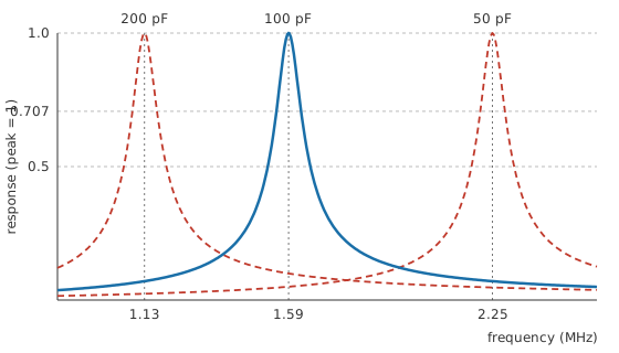
The peak slides along the axis and its width in hertz stays put. That width comes from the resistance and the inductance between them, with the tuning capacitor absent from it, so a receiver built this way is sharper at the top of its tuning range and lets more of the neighbouring station through at the bottom. Q factor and bandwidth puts numbers on that trade.
On the bench, a function generator swept slowly across the range with an oscilloscope watching the response finds the frequency directly. An LCR meter reaches it by a different route, reporting the inductance and the capacitance so the frequency can be worked out, though that route counts only what is inside the two components.
Engineer
Energy changing hands twice a cycle
The coil and the capacitor each obstruct an alternating current, and their two obstructions travel in opposite directions as the frequency changes.
One climbs in proportion to frequency, the other falls in inverse proportion, so they are equal at a single point on the axis. Equate the two expressions, cancel the 2πf that both carry, and what is left is the frequency Layer 2 quoted: one over the square root of the product of the two component values.
That is arithmetic standing in for something physical. A capacitor holding voltage stores energy in its field, and a coil carrying current stores energy in its own. At resonance the two stores are the same size, and the circuit spends every cycle moving the whole of it from one to the other and back again. When the capacitor is at peak voltage the current is momentarily zero and the coil holds nothing; a quarter of a cycle later the capacitor is empty and every joule is in the coil's field.
Worked example — Following one parcel of energy round
At resonance the coil's reactance is 1.0 kΩ and the capacitor's matches it at 1.0 kΩ; the value they share is the square root of the inductance divided by the capacitance.
Let the capacitor swing to a peak of 10 V. A quarter of a cycle later that voltage has gone and the current, set by the same reactance, is at its own peak of 10 mA.
The capacitor at its fullest holds 5.0 nJ. The coil at its fullest holds 5.0 nJ. One parcel, weighed twice.
Energy stored in a capacitor and energy stored in an inductor treat the two stores on their own. Resonance is what those expressions describe once the parts are wired to feed each other, and the source is left with nothing to do but replace what the resistance takes on each pass.
Everything so far assumes the lossless circuit, and a distinction it hides opens up as soon as loss is admitted. The frequency of largest response, the frequency at which the circuit looks purely resistive to its source, and the frequency at which a disturbed circuit rings on its own are one number in the ideal case and three slightly different numbers in a real one. The last of them belongs to the step response, and it sits below the other two:
Put 50 Ω in the loop of the worked example and the damping ratio comes to 0.025, which pulls the ringing frequency below the undamped figure by 497.4 Hz out of more than a megahertz. At that level the distinction is bookkeeping. Keep adding resistance and the gap widens until, at a damping ratio of one, the circuit stops ringing at all and the word resonance stops describing anything.
The algebra also leans on conditions it never mentions. One frequency at a time, since a source carrying harmonics meets a different impedance at each of them, and a harmonic landing near resonance draws a current out of all proportion to its own size. Steady state, with the switch-on transient already decayed. Components whose values hold still, since a core drifting towards saturation or a ceramic dielectric losing capacitance under bias retunes the circuit while it is running.
Professional
Every real part resonates somewhere
A tuned circuit lands where its total inductance and total capacitance put it, and both totals include things nobody drew. Wiring capacitance, a coil's own turn-to-turn capacitance, the input capacitance of whatever the circuit feeds and the probe used to check the answer all join the C; lead and track inductance join the L.
Worked example — Ten picofarads nobody drew
Suppose the layout and the following stage contribute 10 pF alongside the tuning capacitor, taking the total to 110 pF.
Resonance moves down to 1.52 MHz, low by 4.65 %.
The square root is the only thing keeping that error modest, and it does the same job for component tolerance: a capacitor a few per cent out of specification moves the frequency by roughly half as much. Trimmer capacitors and adjustable cores exist because "roughly half as much" is still far too much for a receiver.
The same effect runs in the other direction. A capacitor's leads and internal structure have inductance, a coil's turns have capacitance between them, so each part resonates with itself at some frequency and behaves as the other kind of component above it. That point is the part's self-resonant frequency.
Worked example — Where two ordinary parts stop being what they are
Give a 100 nF ceramic capacitor 2.0 nH of package and lead inductance, an illustrative figure, not a catalogue value. It resonates with itself at 11.25 MHz, and above that it is an inductor.
Give the 100 µH coil 5.0 pF of winding self-capacitance, illustrative again. It resonates at 7.12 MHz and is a capacitor above it.
A decoupling capacitor is therefore chosen by the frequency it has to work at and not by its capacitance alone, and a small part with short connections beats a larger one on long leads well before the tens of megahertz. Its equivalent series resistance decides how deep the impedance notch at self-resonance goes and how much the part still helps on either side of it.
An inductance and a capacitance sharing a node resonate whether anyone intended it. A supply filter built from a series inductor and a shunt capacitor peaks at its own resonant frequency, and a load or a source that excites it there gets amplification of the ripple the filter was fitted to remove; the usual cure is a damping resistor and a little deliberate loss. Cable runs and enclosure cavities resonate as well, and a structure at resonance radiates efficiently, which is one of the places this material meets electromagnetic compatibility.
Where a design needs a resonance sharper or steadier than wound components can hold, the resonator stops being electrical. A quartz crystal resonates mechanically and presents that mechanical behaviour to the circuit as an electrical resonance, at a Q and a frequency stability no coil and capacitor approach. It is the frequency-setting part in oscillators that must hold a frequency to a specification instead of merely reaching one, and the resonant sections inside band-pass and band-stop filters are chosen on the same grounds.
Measurement carries its own trap. Component meters report each part at a chosen frequency and cannot tell you what the assembled circuit does, because the strays that moved the frequency earlier on this page sit inside neither component. Sweeping the finished circuit answers the question honestly, provided the instrument does not join in: a probe across the tuning capacitor lands squarely in the tuned circuit, and on a hundred-picofarad tank a few picofarads of tip capacitance is a visible fraction of the total.
Common mistakes
- Reading resistance into the resonant frequency — it is not in the expression. The coil and the capacitor fix where the peak sits; resistance decides only how sharp and how tall it is.
- Scaling the tuning range linearly with the capacitor — frequency follows the square root, so a four-to-one variable capacitor gives a two-to-one frequency swing and nothing more.
- Trusting the marked values on a high-frequency tuned circuit. Layout capacitance and lead inductance join the totals, and at a hundred picofarads the strays are a measurable share of the tuning capacitor.
- Treating a capacitor as a capacitor at every frequency — above its self-resonance the lead inductance is in charge, and fitting more capacitance in the same package moves the problem the wrong way.
- Assuming a resonance is always one you designed. A supply filter, a run of cable or a coil's own winding capacitance each has a frequency of its own, and the first sign is usually a peak where the response was meant to be flat.
- Confusing the ringing frequency with the resonant frequency. They agree while the loss is small and drift apart as it grows, which starts to matter once the damping ratio is no longer tiny.
Frequently asked questions
What is resonance in an electrical circuit?
The frequency at which a circuit's inductance and capacitance hold equal energy and exchange all of it twice per cycle. Their reactances are equal and opposite there, so they cancel each other, and the circuit responds far more strongly than at any neighbouring frequency.
What decides the resonant frequency?
The inductance and the capacitance, and nothing else. The frequency falls as either value rises, and it follows the square root of their product, so quadrupling one of them halves the frequency.
Do series and parallel LC circuits resonate at the same frequency?
For ideal parts, yes. The consequence differs: the series loop drops to minimum impedance and maximum current, the parallel pair rises to maximum impedance and draws minimum current from its source. Real coil resistance pulls the parallel peak a little low.
Why does a capacitor stop behaving like a capacitor at high frequencies?
Its leads and internal structure carry inductance, which resonates with the capacitance somewhere. Below that point the capacitance is in charge and the impedance falls as frequency rises; above it the inductance is in charge and the impedance climbs again.
Can resonance happen where nobody wanted it?
Routinely. Any inductance sharing a node with any capacitance has a resonant frequency, which covers supply filters, cable runs and coil windings. The symptom is a peak in a response meant to be flat, or an emission where a harmonic happens to land on some structure's resonance.
How is a crystal different from a coil and a capacitor?
A quartz crystal resonates mechanically, and the circuit sees that mechanical resonance as an electrical one. It reaches a Q and a frequency stability that wound components do not, so frequency references are built around crystals.