
Quick Answer
A transistor oscillator is an amplifier whose output is fed back to its own input through a frequency-selective network. It produces a steady tone at the one frequency where the round trip has a loop gain of at least one and no phase shift left over, and it starts itself from circuit noise.
Intuition
An amplifier listening to itself
Hold a microphone in front of the loudspeaker it is feeding and you get a howl. The room, the microphone and the amplifier form a loop; some frequency travels round that loop and comes back larger than it left, so it goes round again, and again, until something runs out of room. That is feedback that has stopped being useful, and it is also, exactly, an oscillator.
The only difference between the howl and a useful oscillator is that one of them chooses its frequency and the other does not. Put something frequency-selective in the loop — a tuned circuit, a crystal, a chain of RC sections — and the loop can only satisfy its conditions at one frequency, so that is the frequency you get.
There are two conditions, and both have to hold at the same frequency.
The signal has to come back at least as large as it left. A loop gain below one means every trip round is smaller than the last, and whatever started dies away.
And it has to come back in step. A signal that returns half a cycle late fights the thing that produced it. That is negative feedback, which is what makes amplifiers well behaved, and it is the opposite of what is wanted here.
Get both at one frequency and the circuit produces a tone with nothing at its input but the noise it started from. Get the second one wrong and you have built a rather good amplifier by accident.
Practitioner
The circuit, and the loop inside it
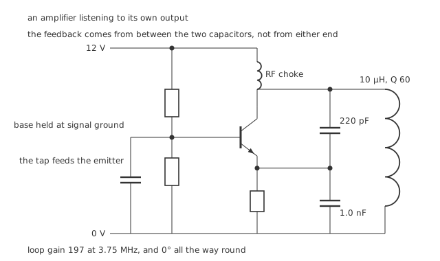
The feedback comes from between the two capacitors, not from either end.
This is a Colpitts oscillator, named after the arrangement that picks the frequency: a coil in parallel with two capacitors in series, with the feedback taken from the junction between them.
Three things on the schematic decide whether it works.
The base is held at signal ground by a bypass capacitor. That makes the stage common-base for the signal — in at the emitter, out at the collector — and a common-base stage does not invert. This matters enormously and is easy to miss.
The feedback comes from the tap between the two capacitors. Taken from either end of the pair instead, it would be either the full output or nothing, and the circuit would not oscillate.
The tank sits at the collector, fed through a choke that passes the bias current and blocks the signal.
Worked example — The frequency, and the gain around the loop
The two capacitors are in series as far as the coil is concerned: 220 pF with 1.0 nF gives 180 pF. With 10 µH that resonates at 3.75 MHz.
At that frequency the coil's reactance is 235.5 Ω, and a coil of 60 presents a parallel resistance of 14.1 kΩ at resonance — which is the load the transistor sees.
Biased at 2.0 mA, the transistor's transconductance at 25.9 mV is 77.4 mS, so the stage's gain into that tank is 1093.
The capacitive divider sends back the fraction 0.180 of it, so the loop gain is 197.
Nearly two hundred times more than the one it needs. That is deliberate, and the fourth layer explains what it costs.
Engineer
The two conditions, and where they meet
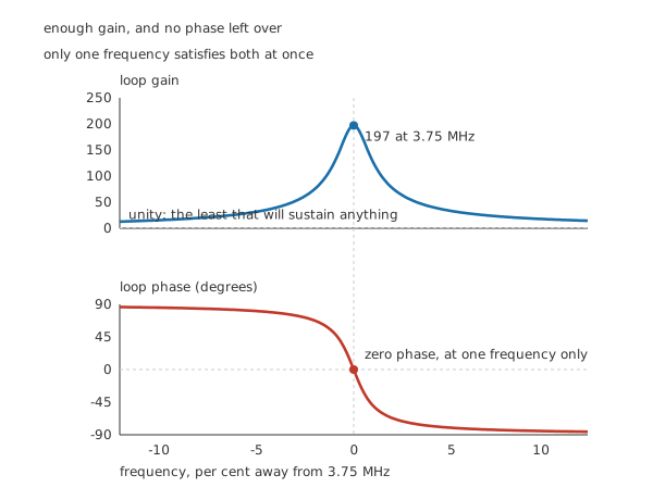
Enough gain, and no phase left over — only one frequency satisfies both.
The conditions have a name, the Barkhausen criterion, and the figure is the whole of it: a magnitude that must reach one, and a phase that must reach zero, at the same place.
Following the phase around this loop, one stage at a time:
- The emitter rises. The base is held still by its bypass capacitor, so the base-emitter voltage falls, the collector current falls, and the collector voltage rises. In phase — a common-base stage does not invert.
- At resonance the tank is purely resistive, so the collector voltage stays in phase with the current making it. Still in phase.
- The capacitive divider is a plain attenuator with nothing reactive left over at resonance, so the tap follows the collector. Still in phase.
Round trip: nothing. The disturbance reinforces itself, and it does so at exactly one frequency, because that third step is only true where the tank is resistive.
Away from resonance the tank becomes reactive and the phase walks off — inductive below, capacitive above — so the loop condition fails on both sides. That is the selectivity a tuned circuit buys, and its sharpness is the coil's 60.
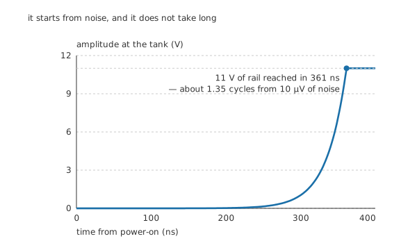
It starts from noise, and it does not take long.
Worked example — Where the signal comes from, and how fast it arrives
Nothing drives this circuit. It starts from whatever is already there — thermal noise in the resistors, shot noise in the junction, the step when the supply comes up. Call it 10 µV.
Every trip round the loop multiplies what is present, so the amplitude grows exponentially. The growth rate follows from the excess loop gain and the tank's stored energy: 38.5 M per second here.
Starting from 10 µV, that reaches 11 V — the rail less the 1.0 V the transistor needs — in 361 ns, which is about 1.35 cycles at 3.75 MHz.
And then it stops growing, because it has run out of supply. With a loop gain of 197, nothing gentler than the rail limits the amplitude. The device clips, the average gain over a cycle falls to exactly one, and the oscillation settles.
That is an honest description of a working oscillator and also a description of a distorted one: a hard clip is rich in harmonics. Designs that care about waveform purity use far less excess gain and an explicit limiting mechanism — a thermistor, a diode clamp, or automatic gain control — so that the loop gain is reduced smoothly rather than by clipping.
Professional
What the frequency actually depends on
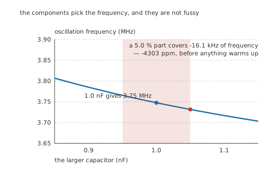
The components pick the frequency, and they are not fussy.
Worked example — What a five per cent capacitor does
The nominal 1.0 nF gives 3.75 MHz. A part at the top of a 5.0 % tolerance gives 3.73 MHz instead.
That is -16.1 kHz — -4303 parts per million — before anything has warmed up, moved, or aged.
Temperature adds its own. At 100 parts per million per degree, a 30 °C rise moves the frequency by -270 ppm.
Note which is larger. The tolerance dominates, and it is a one-time error you can trim out. The temperature drift is smaller and you cannot, which is why an LC oscillator that has been set on frequency still wanders.
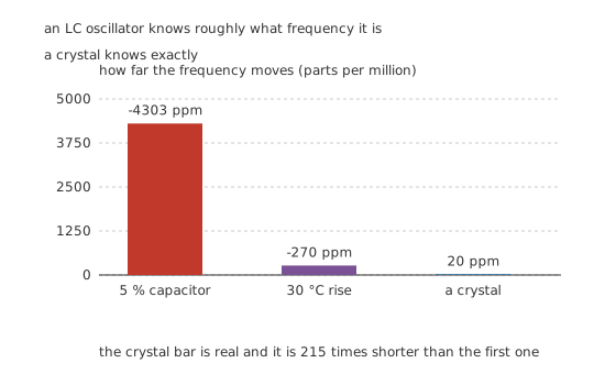
An LC oscillator knows roughly what frequency it is; a crystal knows exactly.
A crystal holds to 20 parts per million — 215 times better than the component tolerance above — and it does so for the same reason the LC tank works at all, only more so. A quartz plate is a mechanical resonator with a Q in the tens of thousands, so the phase around the loop swings through zero far more steeply, and the loop has correspondingly less freedom about where to sit.
The circuit around it barely changes. A crystal oscillator is the same amplifier with the same two conditions; only the selective element is different.
Four things that follow
The oscillator's frequency is set by the loop, not by the tank alone. The transistor's own capacitances sit in parallel with the tank capacitors and shift the frequency slightly, and they change with bias and temperature. It is why oscillators are trimmed after assembly rather than calculated exactly.
A tank's Q is the whole of its selectivity. A 60 of sixty gives a phase slope steep enough to hold the frequency to a fraction of a per cent. Loading the tank — with the next stage, or with the transistor's own input resistance — lowers that Q and widens the frequency's freedom, which is why oscillators are buffered rather than connected directly to whatever they drive.
Hartley, Clapp and Armstrong are the same circuit with a different tap. A Hartley taps a coil instead of a capacitor divider; a Clapp puts a third capacitor in series with the coil so the transistor's capacitance matters less; an Armstrong uses a separate winding. All of them are ways of getting a defined fraction of the output back, in phase, at one frequency.
Not every oscillator needs a resonator. A ring of inverting stages, or a chain of RC sections that adds up to half a cycle of phase shift, oscillates by the same criterion with far worse stability — and that is often exactly what is wanted for a clock that does not need to be accurate.
Common mistakes
- Taking the feedback from the wrong point — from either end of the capacitor pair rather than between them. One wire's difference, and the circuit becomes a tuned amplifier that never starts.
- Forgetting that the base bypass capacitor sets the configuration — without it the stage is common-emitter and inverts, so the loop phase is 180° and nothing oscillates.
- Designing for a loop gain of exactly one — component tolerance and temperature would then stop it starting. Excess gain is deliberate: 197 here, and it is why the amplitude limits at the rail.
- Expecting a clean sine from a hard-limited oscillator — clipping at 11 V is what sets the amplitude, and clipping generates harmonics. Purity needs a gentler limiter.
- Trusting the calculated frequency — a 5 % capacitor alone moves it 4303 ppm, and the transistor's own capacitances move it further.
- Loading the tank directly with the next stage — that lowers the Q, which widens the phase slope and lets the frequency wander.
Frequently asked questions
What are the two conditions an oscillator must satisfy?
A loop gain of at least one, and a loop phase of zero — both at the same frequency. This circuit has a loop gain of 197 at 3.75 MHz and a phase that passes through zero only there, because only at resonance is the tank purely resistive.
Where does the signal come from when it starts?
From noise. Thermal noise in the resistors, shot noise in the junction, and the step as the supply comes up all contain a component at the loop's frequency. Starting from about 10 µV, the loop grows it to the 11 V rail in 361 ns — roughly 1.35 cycles.
What stops the amplitude growing?
The supply. With a loop gain of 197 and no gentler limiter, the oscillation grows until the transistor clips at 11 V, and clipping brings the average gain over a cycle down to exactly one. It works, and it produces harmonics — which is why oscillators that need a clean sine use much less excess gain and a deliberate limiter.
Why is the feedback taken from between the two capacitors?
Because that tap gives a defined fraction of the output — 0.180 here — with no phase shift. Taken from the top of the pair the feedback would be the whole output; taken from the bottom it would be nothing. The tap is what turns a large stage gain of 1093 into a workable loop gain of 197.
Why is a crystal so much better than an LC tank?
Because its Q is thousands of times higher, so the loop phase crosses zero far more steeply and the circuit has correspondingly less freedom about where to settle. A crystal holds 20 ppm where a 5 % capacitor alone puts this LC oscillator 4303 ppm off — 215 times worse.