
Quick Answer
A parallel RLC circuit puts a resistance, an inductance and a capacitance across one pair of nodes. At resonance the inductive and capacitive branch currents are equal and opposite, so they cancel in the supply line and the impedance rises to a maximum instead of collapsing. Raising the resistance raises Q.
Intuition
Current that circulates instead of passing through
A coil and a capacitor connected across the same two points each take their own current from those points. The coil's share grows as the frequency falls, the capacitor's grows as the frequency rises, and somewhere between them the two are the same size.
Matching sizes alone would settle nothing; the timing does the work. Current in the coil arrives a quarter of a cycle behind the voltage across it, current in the capacitor a quarter of a cycle ahead of it, so the two branches sit half a cycle apart at all times: one is drawing current in while the other is giving it back. Equal in size and opposite in direction, they supply each other, and the source is left with nothing to contribute.
None of that current has stopped flowing. It circulates between the coil and the capacitor, out of one and into the other twice per cycle, without passing through the terminals at all. Only the resistor still draws on the source, and where the resistance is large that draw is tiny. A source being asked for almost no current is facing a very large opposition, so this arrangement reaches its highest impedance at the frequency where the series version of the same three parts reaches its lowest.
Tuned radio front ends and mains-hum traps both rest on that behaviour. One frequency the circuit takes seriously, and everywhere else a coil or a capacitor doing something unremarkable.
Practitioner
Putting numbers on the peak
Branch currents match when reactances match, and that is the condition the series circuit resonates under as well. The wiring decides what happens at the resonant frequency and has no say in where the frequency sits.
The result arrives in radians per second, so divide by 2π for hertz. Only the inductance and the capacitance appear in it. A coil and capacitor paired like this go by the name tank circuit, and the term sticks whether or not a resistor is fitted alongside them.
Worked example — A tank built from the series lesson's coil and capacitor
Put 10 mH and 1.0 µF across each other, then put 10 kΩ across the pair.
Their natural angular frequency is 10 krad/s, which as an ordinary frequency is 1.59 kHz — the identical figure those same two parts give when they are wired in series instead.
At that frequency the two reactive branches take equal and opposite currents, so nothing of either reaches the terminals. What the source faces is 10 kΩ, the resistor on its own.
How narrow the peak is comes from the quality factor, and this is where the two topologies part company:
Resistance sits in the numerator. In the series expression it sits in the denominator, so the same component moves Q in opposite directions depending on how the three parts are joined. Bandwidth still means the span between the two frequencies at which the response has dropped to about seventy per cent of its peak, which is half the power.
Worked example — How narrow that peak is
The three parts above give a Q of 100, and the bandwidth that follows from it is 15.9 Hz.
Centred on 1.59 kHz, that puts the half-power edges at roughly 1.58 kHz and 1.60 kHz. A signal a few tens of hertz off centre already meets a very different circuit.
Swap the wiring and keep the parts, and the reversal shows up as a number. A 10 Ω resistor in series with that coil and capacitor produces a Q of 10; the 10 kΩ resistor across them produces 100. A thousand times the resistance, ten times the Q, and the direction of travel inverted.
Reaching for the series expression on this circuit is a quiet way to be badly wrong. Feed the parallel resistor into it and out comes 0.01, low by a factor of ten thousand, with nothing about the answer to suggest anything went astray.
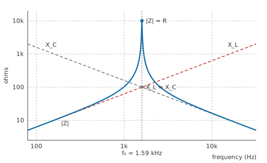
On logarithmic axes the sweep is the series lesson's picture turned upside down. Each reactance is a straight line, the impedance follows whichever of the two is currently the easier path for current, and at the crossing point the pair stops conducting altogether and lets the resistor answer for the whole circuit. A Q of that size compresses the peak into a needle.
Finding it on the bench takes a function generator swept slowly across the range and an oscilloscope watching the voltage across the tank. Sweep too fast past a peak this narrow and it will not have time to build.
Engineer
Why the line current nearly disappears
Parallel branches share one voltage, which makes the voltage the natural reference for everything else and mirrors the series case, where the shared quantity is the current. Each branch takes whatever current its own opposition allows at that voltage, as in any parallel circuit, and Kirchhoff's current law at the top node adds the three branch currents into what the source has to deliver. That addition is a phasor addition, because the three do not peak together.
The resistor's current keeps step with the voltage. The coil's arrives a quarter of a cycle late and the capacitor's a quarter of a cycle early, leaving those two in direct opposition, and phasors sets out that bookkeeping properly.
Worked example — Three branch currents at resonance
Drive the tank from 1.0 V at its resonant frequency. The coil's reactance there is 100 Ω and the capacitor's is 100 Ω.
Equal reactances at a shared voltage means equal currents: 10 mA in the coil and 10 mA in the capacitor. Half a cycle apart, they meet at the node and cancel.
The source supplies the resistor's current and nothing else, which comes to 100 µA. What goes round the loop is 100 times what comes in at the terminals.
That multiplier is Q wearing its third hat. A series circuit at resonance magnifies the voltage across each reactive part by Q; this one magnifies the current in each reactive branch by the same factor. Q factor and bandwidth gathers the readings together and shows they are one number.
Move off resonance and the cancellation degrades from both sides at once, since one branch is becoming easier while the other becomes harder.
Worked example — One octave above resonance
Double the frequency to 3.18 kHz. The coil's reactance doubles to 200 Ω and the capacitor's halves to 50 Ω.
The capacitor now conducts far more readily than the coil, so there is nothing like a cancellation left and the pair behaves as a plain capacitor with a resistor sitting uselessly beside it. Impedance has fallen to 66.7 Ω, close to the capacitor's own reactance and nowhere near the resistor's value.
One piece of the series treatment does not carry over, and it is the piece most often carried over anyway. Series reactances combine as a difference and the impedance follows directly. Parallel branches combine through their reciprocals: the susceptances subtract, and the impedance is the reciprocal of what the branch admittances sum to. Both examples above went through that reciprocal form. The series impedance expression will accept these component values without complaint and hand back a figure, and the figure describes a circuit nobody built. Admittance, the reciprocal of impedance, is simply the quantity in which a parallel circuit is easy, in the same way conductance is the easy quantity for parallel resistors.
Read the circuit as a step response instead and the content is unchanged, only re-denominated. Its damping ratio is 0.005, one over twice the Q. The expression that produces a damping ratio straight from R, L and C is written for the series loop and puts the resistance the wrong way up for this circuit; second-order transients handles the time-domain side, and a lightly damped ring is a sharp resonance seen from the other end.
A few assumptions run underneath all of it without being said. One frequency at a time: a source carrying harmonics meets a different impedance at each of them. Steady state, with the switch-on transient already decayed. Linear parts of fixed value, since a saturating core or a voltage-dependent ceramic retunes the circuit while it is running and leaves the phasor method with nothing to work on.
Something else catches people at the bench. An impedance peak is only visible if the source is willing to let the voltage move. A current source, or any source with substantial impedance of its own, develops a large voltage across the tank at resonance and a small one elsewhere, which is the response the sweep is looking for. A stiff voltage source holds the terminal voltage flat at every frequency and the resonance shows up only in the current it delivers, which is where the peak becomes a dip. It is the same circuit in both cases, and only the shape of the trace has changed.
Professional
The coil decides the tank's Q
A parallel resonant circuit is rarely built with a resistor across it. In most tuned circuits the resistance in the Q expression is not fitted at all: it is the coil's winding loss and the capacitor's equivalent series resistance arriving in disguise, transformed into a resistance that appears across the tank. Coil loss dominates that pair in almost every practical case, so the coil sets the Q of the finished circuit.
The transformation is worth following, because loss enters the coil in series and has to come out in parallel before the Q expression can use it. A coil with reactance X_L and winding resistance r_s has a quality factor of its own, X_L divided by r_s. Provided that figure is comfortably above ten, the same coil is indistinguishable at the terminals from a lossless one with a resistance of X_L squared over r_s across it — equivalently, the inductance divided by the product of the capacitance and r_s. That resistance is the tank's dynamic impedance: the value it reaches at resonance.
Once loss has been converted into a shunt resistance, everything combines the ordinary way:
Worked example — The same tank, with the coil's loss counted
Suppose the coil carries 4.0 Ω of winding resistance and nothing else in the circuit is lossy.
At resonance its reactance is 100 Ω, so the coil's own quality factor is 25 and it presents a dynamic impedance of 2.5 kΩ.
Fit the 10 kΩ resistor as well and the two sit in parallel, giving 2.0 kΩ. Q falls to 20 and the bandwidth opens out to 79.6 Hz.
The resistor that looked like the whole story in Layer 2 turns out to be the minor partner. Everything connected across a tank joins that parallel group, and a parallel group is governed by its smallest member: the stage the tank feeds, the source driving it, and the probe used to look at it are all in there. A high-impedance scope probe is harmless resistively, but its tip capacitance of ten or fifteen picofarads — an illustrative figure, not a catalogue value — lands straight across the tank capacitor and moves the frequency being measured. In the series loop, loss adds into a sum and the largest term dominates. Here it enters a sum of conductances, where the smallest resistance sets the result.
Coil loss also pulls the frequency of maximum impedance slightly below the value the LC expression gives, by a fraction that depends on the square of the winding resistance. Above a coil Q of about ten the shift is smaller than the tolerance on either component and is normally ignored.
Driving a real load from a tuned circuit is therefore a matching problem. Connect a low-impedance load straight across the tank and the Q collapses with it. The usual answer is to attach the load to part of the tank instead: a tap partway along the coil, or the capacitor split into two in series with the load taken from their junction. Either way the load appears across the whole tank multiplied by the square of the turns or capacitance ratio, so a modest ratio turns an awkward load into a tolerable one. Impedance matching is the same transformation seen from a different direction.
The L-to-C ratio is the other lever, and it is free in the sense that many pairs give the same frequency. At a fixed resonant frequency, more inductance with proportionally less capacitance raises the dynamic impedance and the reactance at resonance together. It also means more turns, more winding resistance and more self-capacitance, so the gain is real but bounded. A coil's self-capacitance in this circuit simply adds itself to the tuning capacitor, which lowers the frequency and puts a floor under how small the capacitor can usefully be.
Loss is frequency dependent, so a Q measured at one frequency does not transfer to another: winding resistance climbs as current crowds towards the conductor surface, and core material absorbs energy of its own; the capacitor's ESR moves with frequency too. An LCR meter reports the parts individually at a chosen frequency, and sweeping the assembled tank answers the question more honestly because it counts every loss present. Where the tank is driven hard, core saturation deserves attention, since the circulating current is Q times the current anyone measured at the terminals.
Parallel resonance is put to work wherever a high impedance at one frequency is wanted alongside a low impedance everywhere else. It is the collector or drain load that gives a tuned amplifier its selectivity, the frequency-setting element in LC oscillators, and the trap that blocks one unwanted frequency in band-pass and band-stop filters. A quartz crystal has a parallel resonance a little above its series one, and an oscillator specification will state which of the two the circuit is meant to use, because loading the crystal differently moves the parallel figure and leaves the series figure alone.
Common mistakes
- Using the series Q expression on a parallel circuit — resistance divides in one form and multiplies in the other. The result is wrong by a factor of Q squared and looks entirely plausible on the page.
- Combining the branches as reactances — parallel branches add as susceptances, the reciprocals. Subtract the reactances here and the impedance comes out as though the tank were a series chain, which it is not.
- Expecting the resonant frequency to move when the resistance changes. The inductance and the capacitance fix it between them; resistance only decides how sharp the peak is.
- Sweeping a tank from a stiff voltage source and concluding it has no resonance — a source that holds the terminal voltage constant hides the impedance peak. Feed it from a source with impedance of its own, or watch the supply current instead.
- Rating the coil and capacitor for the current the source delivers — the circulating current between them is Q times larger, and in a high-Q tank that is the figure the parts have to survive.
- Assuming the fitted resistor sets the Q. The coil's winding loss appears across the tank as a resistance of its own, and that resistance is often the lower of the two.
Frequently asked questions
What happens at resonance in a parallel RLC circuit?
The inductive and capacitive branch currents become equal in size and opposite in phase, so they cancel where the branches meet. Only the resistive branch still draws from the source, the impedance reaches its maximum, and the terminal current reaches its minimum.
Why does more resistance raise Q in a parallel circuit and lower it in a series one?
Q measures energy stored against energy lost per cycle. A series resistor carries the full circulating current, so a larger one dissipates more. A parallel resistor sits at the full voltage instead, so a larger one draws less current and dissipates less. Same quantity, opposite arithmetic.
Does a parallel LC resonate at the same frequency as a series LC?
For ideal parts, yes: the frequency depends only on the inductance and the capacitance. Real coil resistance pulls the parallel circuit's peak slightly low, though the shift is normally smaller than the component tolerances.
Where does the current in a tank circuit go if the source is not supplying it?
Round the loop formed by the coil and the capacitor. Energy moves from the capacitor's electric field into the coil's magnetic field and back twice per cycle, and that exchange needs no help from outside except to replace what the losses take.
What is the dynamic impedance of a tank circuit?
The impedance it presents at resonance, which the circuit's loss decides and the reactances do not. For a tank whose loss is mostly coil winding resistance it works out as the inductance divided by the product of the capacitance and that resistance.
How do I connect a load to a tuned circuit without ruining its Q?
Tap it in partway rather than across the whole tank, using a tap on the coil or a split capacitor. The load then appears across the tank multiplied by the square of the ratio, so a small fraction of the tank presents a large equivalent resistance.