
Quick Answer
Kirchhoff's current law states that the currents entering any node of a circuit sum to the currents leaving it, because charge cannot accumulate at a junction. Fix one direction as positive and the signed branch currents at the node add to zero. Any closed surface drawn around a group of nodes obeys the same rule.
Intuition
What the third wire has to carry
Three wires meet under one screw terminal. Current arrives along one of them and leaves along the other two, and the terminal itself is a small piece of brass with no capacity to keep any of it. The arithmetic there is settled before an instrument is connected: what comes in goes out, divided between the outgoing wires in whatever proportions the rest of the circuit decides.
Clamp the incoming wire and read 800 mA. A clamp on one of the outgoing pair reads 500 mA. That fixes the third wire without a meter ever going near it, since it has to carry 300 mA and there is nowhere else the difference could have gone.
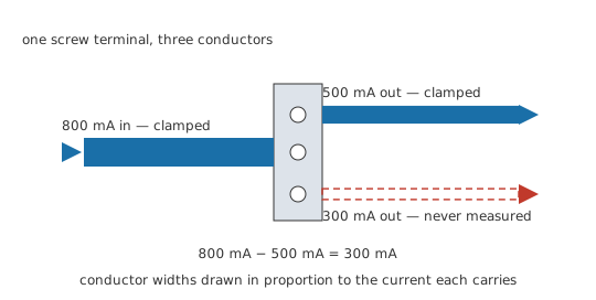
Every carrier that goes into a component comes back out of it. A resistor that has been warm for an hour has returned every electron that entered it; what it consumed was energy, which is a separate account. Charge passes through components and gets redistributed at junctions, and a junction is the one place in a circuit where it has a choice of route.
The word for such a junction is a node, and it covers more copper than a single screw. Everything joined by conductors with no component in between — a length of track, a plane, four legs soldered to one pad — counts as one node at one potential, and the law applies to the group as a whole. That is why the currents in parallel branches, which hang between a pair of nodes, add up to what the supply provides. The companion statement, about voltages around a loop instead of currents at a node, is Kirchhoff's voltage law.
Practitioner
Signs first, then the sum
The law itself is one sentence: the currents entering a node sum to the currents leaving it. What makes it awkward to use arrives a step later, in the bookkeeping, and settling that first removes most of the ways a node equation goes wrong.
Assign a direction to every branch at the node and mark it on the drawing. Take current entering the node as positive and current leaving as negative. The opposite convention works identically, so the choice is arbitrary, and the one thing it has to be is consistent across every branch of every node in the problem. With the directions fixed, the law has a working form: the signed branch currents at a node add to zero.
Arrows drawn before the answer is known will sometimes point the wrong way, and that costs nothing. The algebra returns a negative number for that branch, which reads as this much current, in the direction opposite to the arrow, and it is a complete answer. Erasing the arrow and re-solving is where sign errors get introduced; leave it where it is and read the minus sign.
No single expression can state the law, because a node may join two conductors or twenty while an expression has a fixed number of terms. So the sentence carries the general statement and a formula library holds only the particular case in hand. Here that case is a node fed by one conductor and drained by three:
There are three terms because the example below has three branches; four branches would mean four terms, with the sentence unchanged. Most node problems arrive with the node's potential known and the branch resistances known, so each branch current comes from Ohm's law used backwards and the total is then a sum.
Worked example — One node, three loads, and a clamp that disagrees
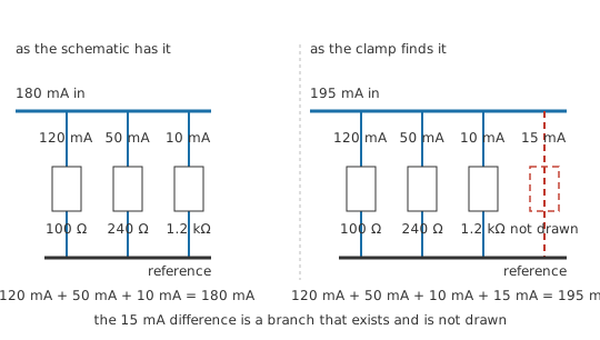
A regulated rail sits at 12 V above the reference, and three loads hang from it — 100 Ω, 240 Ω and 1.2 kΩ — each returning to the reference by its own path. Predict what the supply lead has to carry, then go and measure it.
Every branch has the same voltage across it, so each takes what its own resistance permits. I_1 = V ⁄ R_1 = 120 mA, and the same division on the other two gives 50 mA and 10 mA.
One conductor brings current into the node and three take it away, so the incoming conductor carries the sum of the three: I_T = I_1 + I_2 + I_3 = 180 mA.
A clamp on the supply lead reads 195 mA. Prediction and measurement differ by 15 mA, and the law allows only one account of that: a fourth conductor is attached to the node and it is not on the drawing. Which conductor it is, the number does not say. Contamination bridging the rail to the chassis, a return through a mounting screw or a load someone added without recording it would each produce the same discrepancy. What the discrepancy does establish is that the branch exists and how much it takes.
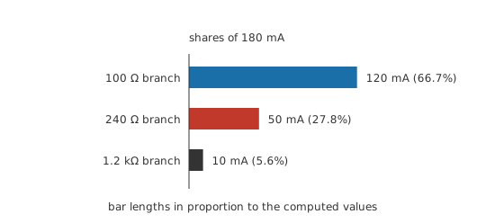
Currents themselves are the awkward quantity to obtain, which is why so much practical work uses the law in the direction shown above: predict the currents from voltages and resistances, then check one of them. Where a total is what you hold and the split between two branches is what you want, the current divider reaches it without the node voltage appearing at all. In a network of any size the systematic version of the same equation, written once per node, is nodal analysis, and the vocabulary it uses — nodes, branches and loops — needs to be straight before you begin.
Engineer
Charge has nowhere to accumulate
Charge is conserved. It is neither created nor destroyed, only moved, and applied to any region of space that statement becomes an accounting identity: the net current flowing into the region equals the rate at which the charge inside it increases. Kirchhoff's current law is that identity applied to a region whose enclosed charge does not increase.
A node is a piece of conductor, and a piece of conductor can hold charge. How much it holds depends on its capacitance to everything around it, the stored charge being that capacitance multiplied by the node's potential above the reference. Hold the potential steady and the stored charge is a constant, a constant has a rate of change of zero, and the net current into the node is therefore zero. Written with directions assigned, that is the statement that the signed branch currents sum to zero. At DC it is exact: one term of the identity is simply zero.
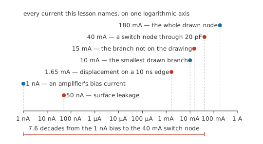
Away from DC a term is being discarded, and its size can be worked out before it goes. A small node on a board — a pad, a via and a short length of track — presents perhaps 5 pF to its surroundings. Take it through a 3.3 V logic transition and its stored charge changes by 16.5 pC. Complete the transition in 10 ns and that charge has to be supplied at an average rate of 1.65 mA, which set against the 10 mA in the smallest branch of the node worked through earlier comes to 16.5 %. During the edge, the currents in the conductors meeting at that node genuinely fail to balance.
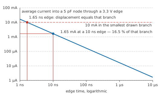
The law survives this because the charge went somewhere identifiable. Capacitance from the node to its surroundings is a branch like any other, carrying current whenever the node's potential moves. Draw it in and the balance is restored; leave it out and a real current has been omitted from a real equation, sometimes by enough to change the answer.
The derivation never required the region to be small. Charge conservation was applied to a region, and a region can be a single junction, a whole subcircuit, or an entire instrument standing on a bench. Draw a closed surface cutting through the wires of a circuit and the same conclusion follows: the signed currents crossing that surface sum to zero, provided the charge enclosed is not changing. A single junction is only the smallest useful case.
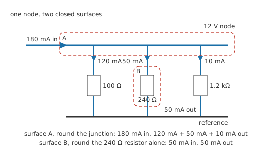
Enclosing two nodes bridged by a voltage source is where that freedom of shape starts to pay. The source's branch current — which the source itself does not determine — never enters the equation at all, since it stays inside the surface and crosses it nowhere. One equation then covers the pair. The manoeuvre is called a supernode, and it is what lets nodal analysis handle voltage sources at all. The same surface drawn around a two-terminal black box forces the current entering one terminal to equal the current leaving the other, and a single current then describes the whole component.
Every step of that argument rests on something that can give way. Constant enclosed charge gives way whenever a node's potential is moving, which is the term sized a few paragraphs above. The claim that the wires carry all the current crossing the surface stops holding once the circuit's dimensions become comparable with the wavelength of the signals in it. At those frequencies the structure is a distributed one, current flows in the fields between conductors as readily as along them, and lumped node equations stop describing the circuit. Neither of those contradicts the opening picture of there being nowhere else for the current to go: in both cases there is somewhere else, and it is a place the drawing did not show. The quietest failure is the one nobody notices at all. A node equation constrains the branches written into it, so a branch omitted from the drawing is a branch omitted from the answer.
Professional
Branches that are not on the schematic
Getting at a current in the first place
A voltmeter takes its reading without disturbing much, whereas reading a current asks for an intrusion. Splice a meter into the conductor and the meter's own resistance joins the branch, reducing the current it came to measure. Put a jaw round the conductor instead and the circuit stays intact, but a clamp meter needs a single conductor it can encircle, resolves tens of milliamperes at best on general-purpose ranges, and on DC carries a zero offset to be nulled before each reading.
Neither is convenient enough to use at every node, so most currents are inferred. A current-sense resistor already in the branch turns the current into a voltage the design can read continuously; elsewhere the drop across a resistance that is present anyway does the same for a one-off measurement, with the loop left closed. Measuring V, I and R sets out the technique. An unbalanced node is therefore usually found as a discrepancy between a prediction and a single measurement.
Displacement current through stray capacitance
Worked example — Currents that stop adding up while the transistor turns on
The drain of a switching transistor is a node like any other. Its copper, the tab of the package and the insulator under it together present 20 pF to the grounded heatsink behind them — an unmarked branch from that node to the reference.
Turning on takes the node through 40 V in 20 ns. Its stored charge changes by 800 pC, and moving that charge in that time is a current of 40 mA averaged over the edge, with a higher peak inside it.
It leaves through the insulator, crosses to the heatsink and returns to the supply through whatever metal is bolted in between. Clamp the drain lead and the source lead during an edge and the readings disagree by about that amount. Both clamps are honest and the law holds. The capacitance is the branch the account left out.
Every node with a fast-moving potential has this branch: switch nodes, clock lines, the ends of transformer windings, a probe tip on a high-impedance point. The current is real and it obeys the law, but it returns along paths the layout chose rather than any the schematic showed, which is where a large part of radiated emission and susceptibility work begins. Designing for it means giving the return a short deliberate path.
Leakage, guards and returns
Slow versions of the same story are easier to overlook. A high-impedance node at 5 V with 100 MΩ of surface contamination to the reference passes 50 nA down that path. On a power rail that is beneath notice. On the input of an amplifier whose own bias current is 1 nA, it is 50 times the current the design allowed for. It moves with humidity and with how recently the board was cleaned, which is what guard rings, conformal coating and post-assembly cleaning exist to control.
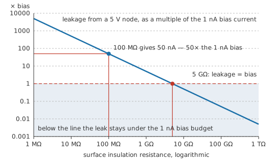
Returns hide a version of their own. A schematic shows one reference symbol repeated; the board or the rack has several conductors joined at more than one point, which is a different circuit. Current leaving a node divides between them by impedance, so a return can arrive back at the supply along a route it shares with something sensitive. Ground loops treats the consequences and ground and reference points the underlying convention. The law holds throughout. The open question is which conductors the drawing merged into one.
Reading an imbalance
A measurement that violates the law tells you more about your model than one that agrees with it. Check the candidates in roughly this order: a probe or clamp not on the branch you believed it was on; a shared return carrying current from a second circuit; a joint or track resistive enough to have split one node into two; a parasitic branch of the kind above; and instrument error, from a DC clamp's offset or a bandwidth too low to see the edge. Work through those and the missing branch is normally found. Charge piling up at the junction is never one of them.
Safety
The switching-node figures above came from a calculation, and no live converter was probed to obtain them. In a converter, that node reaches the supply rail through a device about to conduct, and its potential moves the full bus voltage in nanoseconds; a probe ground lead clipped to such a node makes a low-resistance path with the consequences of a short circuit.
Breaking a conductor to insert an ammeter is the hazard particular to this lesson's subject. On a current range a meter is close to a short circuit, so a slip that lands it across a node instead of in series with a branch turns the instrument into the fault. Clamp the conductor or read the drop across a resistance already present, and isolate and discharge bulk capacitors before opening any conductor at all. The working practices are in electrical safety fundamentals.
Common mistakes
- "The current gets used up as it goes round" — nothing consumes current. A component takes energy from the charge passing through it and passes every carrier on, so the current entering a two-terminal part equals the current leaving it.
- Flipping an arrow halfway through a solution because the answer came out negative. The negative sign already carries that information. Fix the convention at the start, then read the signs as they fall out.
- A node counted as smaller than it is. Everything joined by copper with no component in between is one node. Two pads at opposite ends of a plane are the same node and must appear in the same equation.
- Mixing conventions between nodes — entering-positive at one junction and leaving-positive at the next. Each node's equation is internally consistent and the pair of them still do not combine.
- Treating a failed balance as a failed law. An imbalance locates a branch that is present in the circuit and absent from the drawing. It is a finding, and often the useful one.
- Applying a DC node equation to a fast edge without asking what the node's capacitance is doing. Where the potential moves quickly, the capacitance to everything nearby is carrying current, and an equation that omits it will not close.
Frequently asked questions
What exactly counts as a node?
Any set of points joined by conductors with no component between them. A track, the pad at each end of it, a copper plane and every leg soldered to it are all one node at one potential. Counting a stretch of copper as two nodes is a common source of equations that will not balance.
Does it matter which direction I assume for an unknown branch current?
No. Assign whatever direction is convenient, keep it for the whole problem, and let the sign of the answer tell you the truth. A negative result means the current flows opposite to your arrow and is otherwise a complete answer.
Why is there no single formula for Kirchhoff's current law?
A node can have any number of conductors meeting at it, and a formula has a fixed number of terms. The law is a statement about sums of arbitrary length, so it is written as a sentence and the specific sum is assembled for the node in front of you.
Does the law apply to AC as well as DC?
Yes, applied at each instant to the instantaneous currents. What changes is that capacitance from each node to its surroundings becomes a branch carrying real current, so the balance has to include paths that a DC drawing omits. The law itself holds at every frequency; what has to be revised is the model of which branches exist.
What is a supernode?
A closed surface enclosing two or more nodes, treated as one for the purposes of writing a current equation. It is used when a voltage source bridges two nodes: the source's own current is unknown but internal to the surface, so it never appears, and one equation covers both nodes.