
Quick Answer
A clamp meter measures the current in a conductor from the magnetic field around it, with the jaw closed around the wire and nothing disconnected. It reads the net current its opening encloses, so a jaw closed around both conductors of a cable reads nothing at all.
Intuition
A measurement that touches nothing
A clamp meter is a current meter with a hinged jaw on top. The jaw opens, goes around a conductor that is carrying current, and closes again. Nothing is cut, nothing is unplugged, nothing is unsoldered, and the circuit does not know the instrument is there.
A warehouse scanner reads the tag through the side of a sealed box. It never opens the box, and it does not need to: what it is reading was always leaking out. A clamp meter works the same way on a conductor. Current makes a magnetic field around itself whether anyone is looking or not, and the jaw is there to collect it.
The field is not large. Around a single conductor carrying 45.0 A, at the 12.0 mm radius of a typical jaw, it comes to 750 µT, which is roughly fifteen times the earth's own field and small enough that the instrument spends most of its design effort on collecting it properly.
Then there is the fact that catches everyone once. The jaw does not read a current; it reads the net current through its own opening. Close it around one conductor of a two-core flex and it reads 45.0 A. Close it around the whole flex, line and return together, and the two currents cancel inside the opening: the display settles at 0 A, and the appliance at the end of the flex goes on working exactly as before.
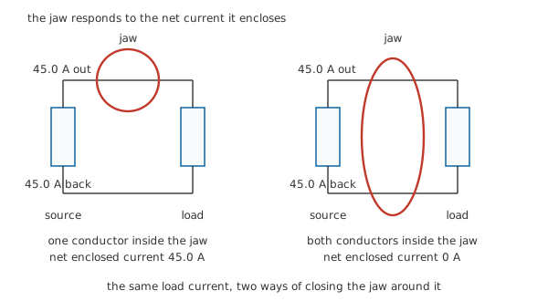
The instrument is honest in both pictures. Only one of them asks the question you meant.
Practitioner
Putting the jaw where it belongs
The sequence is short, and most of it is about what goes inside the jaw rather than what the display says.
- Separate one conductor. Line and return have to be apart before there is anything to read. On a moulded flex that means a break-out lead, not a knife.
- Choose the function before the jaw goes anywhere. On meters offering both, AC and DC current are different sensors, and a DC clamp wants its zero set with the jaw closed and empty.
- Pick a range that suits the current you expect, or let the instrument autorange.
- Close the jaw fully. The mating faces are a magnetic joint as much as a mechanical one, and grit, paint or a half-latched catch all read low.
- Centre the conductor, and hold the jaw still while the reading settles.
- Note what you clamped. A current reading with no record of which conductor it came from is an anecdote.
Range choice deserves a paragraph of its own, because a clamp built to reach hundreds of amps spends most of its life near the bottom of its span. Our 45.0 A conductor sits above a 40.0 A range, so the instrument has to be on the 400 A one, where the reading is 11.25 % of full scale. A 500 mA current on that range is 0.125 % of it, which is the territory where a specification's fixed term swamps its proportional one, as accuracy, resolution and measurement error sets out.
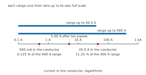
Both ranges start at zero. What separates them is where they stop, and how much of the span your reading is using.
There is a way out of the bottom of the range, and it is one of the more satisfying tricks on a bench. Pass the conductor through the jaw more than once. The jaw counts ampere-turns, so 10 passes of the same wire look to it like 5.00 A instead of 500 mA, and you divide the reading afterwards. The relationship is the transformer's:
With one pass the sensing winding carries 250 µA and its burden develops 2.50 mV; with ten it carries 2.50 mA and develops 25.0 mV, ten times the signal from the same circuit for the price of some slack cable.
Position inside the opening is the other thing worth a number. Where the sensor is a single element in the jaw wall rather than a closed magnetic path, what it sees depends on how far away the conductor is. Centred, it sits 12.0 mm away and sees 750 µT. Pull the conductor 4.0 mm nearer, to 8.0 mm, and the field rises to 1125 µT, 50.0 % high. Push it the same 4.0 mm the other way, to 16.0 mm, and it falls to 562.5 µT, 25.0 % low.
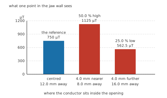
These are the numbers for the worst case, a single sensing point. A well-closed magnetic path collects the field all the way around instead, and cares far less. Real instruments sit somewhere between the two and publish a position error of their own.
Safety
The flag on this lesson is not there because the instrument is dangerous. It is there because the alternative is.
Reading a current any other way means opening the conductor and putting a meter in the gap, and on anything connected to a supply that is a job most people should decline. A clamp goes around the outside of the insulation and leaves the circuit whole, which is why it is the right tool for mains and for anything carrying serious current. That argument holds only while the instrument is sound.
The jaw's insulation and the instrument's rating are what keep the outside of the jaw at your potential rather than the conductor's. Use a meter whose category rating covers where you are working, and read CAT ratings and safe working voltages before assuming a number on a case covers your job. A cracked jaw, a chipped mating face or a dropped instrument is a defect, not a cosmetic complaint. Clamp around insulated conductors: bare conductors and busbars need an instrument built and rated for that use, and the hazard there is contact rather than measurement.
One hazard belongs to current transformers generally rather than to clamp meters. A separate current transformer with its primary energised must never have its secondary opened, because the burden across it is what holds its terminal voltage down. A clamp meter has that burden built in and permanently wired, which is one more reason the jaw is not a place to improvise.
The general working practice for live circuits is in electrical safety fundamentals and is not repeated here.
Engineer
Two instruments wearing one shape
Two quite different sensors live behind the same hinged jaw, and knowing which one you are holding explains most of what a clamp meter can and cannot do.
Both start from the same place. A long straight conductor surrounds itself with a field whose strength falls off with distance:
with the constant 1.2566 µH/m setting the scale. At the 12.0 mm jaw radius our 45.0 A gives 750 µT; at 24.0 mm, twice as far, 375 µT, exactly half. That one-over-distance shape is where Layer 2's position arithmetic comes from.
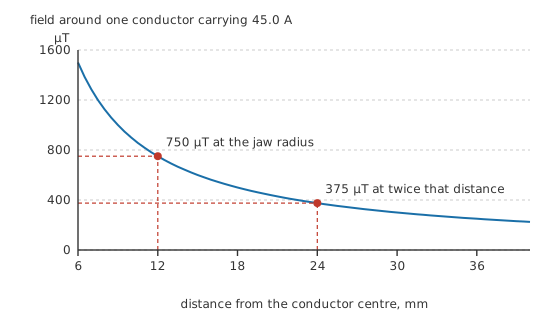
Nothing about this curve is specific to a clamp meter. The jaw radius simply picks a point on it.
Why the jaw is made of iron
Half a millitesla is a thin signal to build an instrument on, so the jaw is not empty. It is a magnetic circuit: a split ring of high-permeability material that closes around the conductor and gives the field a path far easier than air. Ampere's law taken around that path gives a magnetising field of 596.8 A/m for our conductor, and the material's response to it is the same linear relation any core obeys:
With an illustrative relative permeability of 300, that magnetising field produces 225 mT inside the core, some three hundred times what the same current makes in open air. The arithmetic ignores the reluctance of the gap every jaw has to have, so read it as the size of the prize rather than as a measurement. It is also why a clamp cares so much about a clean, fully closed joint: the gap sits in series with the whole magnetic path and a small one dominates it.
The coil, its secondary and its burden
An AC clamp is a current transformer. The conductor is the primary, a single turn threading the core, and a winding on the core is the secondary. Instead of being left open, the secondary is closed through a small resistance called the burden, and the instrument measures the voltage across that burden.
Worked example — From the conductor to the display
A conductor carrying 45.0 A threads the jaw and is the primary, with 1 turn. The secondary wound on the core has 2000, so it carries 22.5 mA.
That current runs around a closed loop whose only significant element is the burden resistor, 10.0 Ω, developing 225 mV across it and dissipating 5.06 mW in it.
Everything after that is scaling: 5.00 mV/A of burden voltage for every amp in the conductor, which the instrument turns into digits.
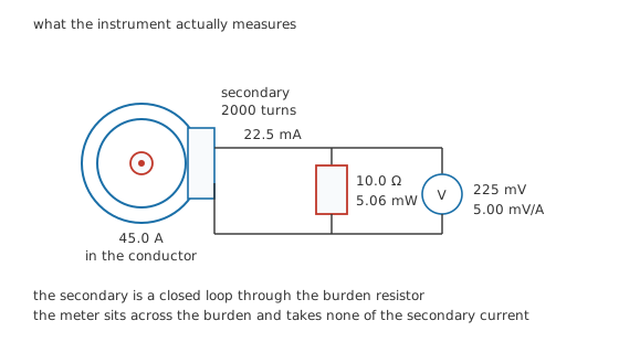
The secondary loop is closed through the burden, and the meter reading that burden takes none of the current.
The high ratio is what makes the arrangement manageable: two thousand turns divide the conductor's current down to something a small resistor can carry without complaint. The same reasoning turns up wherever turns ratios trade current for voltage.
The element that answers to a steady field
A coil answers to a changing field. Hold the current still and it produces nothing, which is why a plain AC clamp reads a dead zero on a battery cable quietly delivering hundreds of amps. Reading that current needs a sensor that responds to the field itself, usually a Hall element in a gap cut in the core.
Take an illustrative element with a Hall coefficient of 0.00040 cubic metres per coulomb and a thickness of 200 µm, biased with 5.00 mA. In the open field beside our conductor it would give 7.50 µV, below the noise of most things you could build to read it. In the core's concentrated field it gives 2.25 mV, which is an amplifier's ordinary day's work. The core is not a refinement here; it is what makes the measurement exist.
What each one hears
The two sensors have opposite weaknesses at the bottom of the frequency range. Model the coil's roll-off as a single corner at an illustrative 20.0 Hz: at the corner itself the instrument reads 70.7 % of its mid-band value, at 50.0 Hz it has recovered to 92.8 %, and below the corner it falls away towards nothing. The Hall element is flat all the way to a steady current, and pays for it with offset and drift instead.
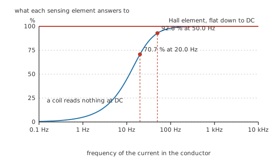
The corner drawn here is an illustrative one. Its position varies with the core and the burden, but the shape does not.
Professional
The readings a clamp gives away
A clamp buys its convenience with accuracy, and the trade is better stated than discovered.
A clamp's accuracy is usually written as a percentage of reading plus a fixed term, and the fixed term dominates whenever the current is a small fraction of the range, as Layer 2's 11.25 % reading already hints. Add the position error, the jaw's own gap and whatever the neighbouring cables contribute, and a clamp reading is comfortably the least precise of the ordinary current measurements. A current-sense resistor beats it by an order of magnitude and needs the circuit broken to fit one, which is the whole trade in a sentence.
A DC clamp has an extra ritual. The Hall element's offset drifts with temperature and with whatever the core last remembered, so the zero button means it. Close the jaw on nothing, zero it, take the reading, and re-zero whenever the jaw has been near something magnetic or the instrument has changed temperature. A reading taken without that step can be wrong by more than the current you were after.
Waveform matters here as much as it does on a handheld meter. The sensor reports the field faithfully; what the instrument does with it afterwards is a design choice, and a mean-responding AC clamp on a variable-speed drive, a dimmer or a rectified load is being asked a question it was never calibrated for. True RMS earns its money on a clamp, because the currents worth clamping are so often chopped.
Some jobs need a different jaw. Flexible current probes replace the rigid core with a coil on a bendable former, giving up the core's concentration and gaining the ability to go around a busbar or a whole bundle; they read AC only. Fast events need a probe designed for them and an oscilloscope behind it, because a clamp meter averages over a good fraction of a second and a motor's starting surge is over before the display has decided anything.
One property is worth ending on. A clamp takes almost nothing from the circuit it measures. An ammeter in series inserts a shunt and steals a share of the loop's voltage, which is the whole subject of meter loading effects; a clamp's only cost is a little extra reluctance around the conductor. The instrument that disturbs a circuit least is also the one that measures it worst, and choosing between them is what measuring voltage, current and resistance is really about.
Common mistakes
- Clamping the whole cable instead of one conductor. Line and return cancel inside the jaw and the display sits near zero, which reads as a dead circuit rather than as the wrong question.
- Expecting a coil-based clamp to read a direct current. It cannot, at any price, and a meter that does it has a Hall element or a fluxgate in the jaw.
- Taking a DC reading without zeroing the instrument first, with the jaw closed and empty.
- Reading a small current on a range built for hundreds of amps and quoting the result to the last digit. Pass the conductor through the jaw several times instead, and divide.
- Letting the conductor lie against one side of the opening, or closing the jaw on grit, paint or a half-latched catch.
Frequently asked questions
Why does my clamp meter read nothing on a mains flex?
Because the jaw is around both conductors and it responds to the net current inside its opening. The current going out to the appliance and the current coming back are equal and opposite, so they cancel. Separate one conductor with a break-out lead and the reading appears.
Can a clamp meter measure DC current?
Only if it has a Hall element or a fluxgate in the jaw, which is what the "AC/DC" on the case means. A coil responds to a changing field, and a steady current does not change. DC clamps also need zeroing on an empty jaw before each reading.
How do I read a current far below the meter's range?
Wind the conductor through the jaw several times. The jaw counts ampere-turns, so ten passes present ten times the current, and you divide the reading by ten afterwards. Nothing is connected and nothing is broken to do it.
Does a clamp meter load the circuit it measures?
Almost not at all. There is no shunt in the path and no burden voltage taken from the circuit, only a small change in the reluctance around the conductor. That is the one measurement where the instrument's effect on the circuit can be ignored outright.
Does it matter where in the jaw the conductor sits?
Yes, and how much depends on the design. An instrument built around a well-closed magnetic path collects the field all the way round the conductor and cares little. One relying on a single sensing element is at the mercy of distance, and the arithmetic in Layer 2 shows what that can cost. Centring costs nothing, so centre it.