
Quick Answer
The turns ratio is the primary turns divided by the secondary turns. It scales voltage in proportion and current in inverse proportion, and because impedance is voltage over current it scales impedance by the ratio squared. That squaring is what makes a transformer a matching device.
Intuition
Changing what the source thinks it is driving
A transformer changes voltage and current together, in opposite directions. Something less obvious follows from that: it also changes what the source on one side believes is connected to the other.
Impedance is voltage divided by current. Step the voltage down by twenty-five and step the current up by twenty-five, and the ratio between them at the input has changed by twenty-five squared. An eight-ohm loudspeaker on the secondary of a 25:1 transformer looks, from the primary, like five thousand ohms — and the source has no way to discover otherwise.
That is why the same device appears twice in this course under two apparently different jobs. Wound for the grid it moves power between voltage levels. Wound for a signal it makes a mismatched source and load look matched to each other, which is the impedance matching problem solved with copper instead of active circuitry, and the gearbox picture that lesson uses fits here without modification: the same engine, the same wheels, and a ratio in between that lets each work where it is happiest.
Matching is worth doing wherever a source has a fixed internal impedance it cannot change and a load has a fixed impedance you would not want to change: valve output stages into loudspeakers, radio-frequency stages into antennas, microphones into preamplifiers. It is worth being clear from the start that this is a signal technique. Layer 4 explains why matching is exactly the wrong thing to do in a power supply.
Practitioner
Turns, volts, amps and ohms
The two working relationships restate what how transformers work established, and the third follows from them by division.
Worked example — Matching a loudspeaker to a 5 kΩ source
A source that wants to see 5.0 kΩ and a loudspeaker of 8.0 Ω need a turns ratio of 25.0.
Checking it forwards: 25.0 squared, times 8.0 Ω, gives 5.0 kΩ.
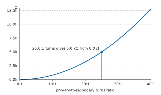
The curve is a parabola, which is the practical warning: impedance matching is sensitive to turns ratio in a way voltage conversion is not. Get the ratio ten per cent wrong and the voltage is ten per cent wrong, while the impedance is twenty-one per cent wrong.
Worked example — The same transformer, working
With 1250 primary turns and 50 secondary turns, 50 V across the primary gives 2.0 V across the loudspeaker, which draws 250 mA.
That secondary current means 10.0 mA in the primary, so the source delivers 500 mW and the loudspeaker receives 500 mW.
Dividing the primary voltage by the primary current, the source sees 5.0 kΩ — the reflected impedance, arrived at from measurements rather than from the ratio.
Notice that nothing has been transformed except the ratio. The same watts arrive at the loudspeaker as leave the source, exactly as an ideal transformer requires, and the matching has cost nothing in power. What it has changed is the terms on which those watts are delivered.
Reading the last line of that example the other way round is the habit worth forming. The reflected impedance is not a property the transformer advertises; it is simply what the primary voltage divided by the primary current comes to once a load is connected. Take the load off and the primary current collapses to the magnetising current alone, so the source sees a very high impedance instead. A matching transformer with an open secondary is not matching anything, which is why an output transformer left unloaded and driven hard is a good way to destroy the stage feeding it.
The turns ratio itself is quoted in two conventions and both appear on datasheets. Some parts are labelled by their turn ratio, 25:1 here, and some by their impedance ratio, 5000:8 or 625:1 for the same component. Neither is wrong and confusing them is a factor of twenty-five, so the safe habit is to check which one a figure is by dividing the two impedances and seeing whether the answer is the number printed or its square.
Engineer
What matching is actually worth
The reflected-impedance relationship is not an extra property of transformers; it falls out of the other two by division. Secondary voltage is the primary voltage times the turns ratio one way, secondary current is the primary current times the turns ratio the other way, so the ratio of voltage to current — the impedance — carries the turns ratio twice. Once for voltage and once for current, hence the square.
Whether that is useful depends on the source. A source with negligible internal impedance does not need matching: it will drive whatever you connect. A source with a substantial internal impedance delivers its most power into a load equal to that impedance, which is maximum power transfer, and a transformer is how you make an unequal load look equal.
There is a direction convention buried in the impedance entry that repays a moment's attention. It is written for the impedance seen at the primary given a load on the secondary, so a step-down transformer, with more primary turns than secondary, reflects a small load up to a large one. Turn the same transformer round and the ratio inverts along with everything else: the same component that makes 8 ohms look like 5 kilohms one way makes 5 kilohms look like 8 ohms the other. The winding is untouched; only the choice of which side is driven has moved.
Worked example — A 5 kΩ source and an 8 Ω loudspeaker
A source of 100 V behind 5.0 kΩ, matched, drives 10.0 mA and delivers 500 mW to the load.
Connect the 8.0 Ω loudspeaker straight across it instead and 19.97 mA flows, of which the loudspeaker receives 3.19 mW — a factor of 157 less.
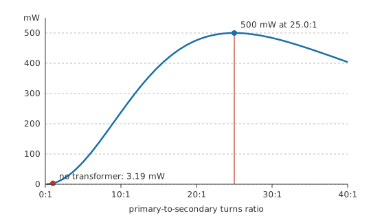
A factor of a hundred and fifty-seven in power, from a component that consumes none of it, is as close to a free lunch as engineering offers. The curve also shows the shape of the penalty for getting it wrong: the peak is broad, so a ratio anywhere from about 15:1 to 40:1 stays within a few decibels, and the drop only becomes severe when the mismatch runs into an order of magnitude.
What the argument does not say is misread often enough to be worth spelling out. It does not say the transformer creates power. The extra watts come from the source, which was previously unable to deliver them into a load it could not drive, and which is now working into an impedance it is comfortable with.
Nor does it say matching is efficient. At the matched point the source dissipates internally exactly as much as it delivers, so half the total is wasted inside the source. That is entirely acceptable when the source is a signal stage whose job is to deliver a signal, and quite unacceptable when it is a power supply whose job is to deliver watts.
Professional
Where a real matching transformer gives out
An ideal transformer works at every frequency. A real one works over a band, and both ends of that band come from inductance.
At low frequencies the primary's own inductance is the problem. It sits in parallel with the reflected load, and as frequency falls its reactance falls with it until it shunts the signal away entirely.
Worked example — The low-frequency corner
A primary inductance of 20 H working against 5.0 kΩ rolls the response off below 39.8 Hz.
At high frequencies leakage inductance takes over. That is the flux which fails to link both windings, it appears in series with the signal path, and its reactance rises with frequency until it dominates.
Worked example — The high-frequency corner
Leakage of 30 mH against the same 5.0 kΩ rolls the response off above 26.53 kHz.
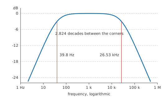
Both corners above take the 5 kΩ source resistance alone as the damping — the full matched circuit, source and reflected load together, does a little better at both ends, but the source alone is the simpler bound and the one that matters when you're picking a transformer. Between the two corners lies 2.824 decades of usable response, which comfortably covers audio and is why output transformers were practical long before semiconductors were. Winding capacitance adds a third limit above the leakage corner, usually as a resonance rather than a clean roll-off, and it is why a wide-band transformer is wound in interleaved sections rather than as two simple coils.
Four points are worth carrying forward from here.
Matching is for signals, not for power. A power supply wants its source impedance as low as possible so that regulation is good and loss is small; deliberately matching it would throw half the energy away inside the supply. When you see a transformer in a power path it is there to change voltage or to isolate, and when you see one in a signal path it may well be there to match.
The ratio, not the transformer, does the matching, and the ratio is fixed at manufacture. Tapped secondaries exist for exactly this reason: an audio line transformer with several taps offers several ratios, and choosing the tap chooses the reflected impedance.
Reflected impedance carries phase as well as magnitude. A reactive load reflects as a reactive impedance scaled by the same squared ratio, so a loudspeaker whose impedance rises at resonance presents that rise to the source, multiplied by six hundred and twenty-five in this example.
Matching is not the only reason to reach for a transformer in a signal path. Isolation breaks ground loops, and a transformer converts between balanced and unbalanced signalling without any active circuitry — the balun that appears wherever a coaxial feed meets a balanced antenna. Those uses often matter more than the impedance ratio, and transformer types sorts out which construction offers which.
Common mistakes
- Confusing the turns ratio with the impedance ratio — impedance scales as the square. A 25:1 transformer is a 625:1 impedance transformation, and quoting the wrong one is a factor of twenty-five error.
- Matching a power supply to its load — maximum power transfer is a fifty per cent efficient operating point. Supplies want a low source impedance and good regulation, not a match.
- Assuming the ratio holds at every frequency — primary inductance limits the bottom of the band and leakage inductance the top. Outside that band a matching transformer stops matching.
- Forgetting that reactance reflects too — the reflected impedance is the load's whole impedance, phase included, multiplied by the ratio squared. A load that peaks at resonance presents an amplified peak.
- Treating the reflected impedance as something the source can detect — it cannot. That is the point, and it is also why a fault on the secondary appears at the primary as a change of impedance rather than as anything more informative.
Frequently asked questions
Why does impedance scale as the square of the turns ratio?
Because impedance is voltage divided by current, the transformer multiplies voltage by the ratio and divides current by it, and the two effects compound. The ratio therefore appears twice in the quotient.
Does a matching transformer amplify?
No. It delivers the same power at a different combination of voltage and current. Any increase in the power reaching the load comes from the source, which could not previously drive that load effectively.
Why is impedance matching wrong for a power supply?
Because a matched source dissipates as much internally as it delivers, so the arrangement is fifty per cent efficient by construction. A supply is designed for a low source impedance and good voltage regulation instead.
What sets a matching transformer's bandwidth?
Primary inductance at the low end, since it shunts the signal as its reactance falls, and leakage inductance at the high end, since it blocks the signal as its reactance rises. Winding capacitance adds a resonance above that.
How wrong can the turns ratio be before it matters?
The power peak is broad, so being out by a factor of about two costs only a couple of decibels. The penalty becomes serious around an order of magnitude, and the impedance error is always twice the ratio error in percentage terms.
What is a balun?
A transformer used to convert between a balanced signal, carried on two conductors of equal and opposite potential, and an unbalanced one referenced to ground. It often performs an impedance transformation at the same time, but the balance conversion is its purpose.