
Quick Answer
Impedance matching is the transformation of a load's impedance until the source sees its own resistance looking back, which is the condition for the largest possible power transfer. A transformer or a reactive network does the transforming without consuming energy. Where the source carries reactance, the matched load is its complex conjugate.
Intuition
The gearbox between source and load
An engine pulls hardest at speeds that have nothing to do with how fast the wheels need to turn. A gearbox sits between the two and trades one for the other, so the engine keeps working where it works well and the wheels still get what they need. Nothing inside the gearbox makes power. It changes a ratio, and that is enough.
Sources and loads have the same disagreement. Every source has some resistance of its own, fixed by whatever is inside it, and it hands over the most power when the load across its terminals happens to equal that figure. Loads rarely oblige. A loudspeaker is a few ohms while a radio output stage is built around tens, and a piezo element behaves like something enormously larger than the amplifier sitting in front of it.
Impedance matching is the electrical gearbox. A transformer, or a small arrangement of coils and capacitors, goes between the two and makes the load look like a different number of ohms from the source's side of it. The load itself has not changed at all. What changes is the ratio the source is presented with, and with it the amount of power that gets across the join.
Gearing costs something, here as anywhere. When the two are matched, as much power stays inside the source as leaves it, which is a fair bargain for a faint signal and a poor one for a mains supply. Maximum power transfer works through why the split lands at half. This lesson is about the gearbox that gets you there.
Practitioner
Making a small load look large
Reduce whatever feeds the terminals to its Thévenin equivalent and the source becomes two numbers: an open-circuit voltage and a resistance. Those two set a ceiling on what any load can draw out of it, and the ceiling has a name of its own, the source's available power.
Collecting all of it needs a load equal to the source resistance. Where the load is the wrong size, a transformer changes what the source sees. An ideal one passes the same power on both sides, so a step down in voltage is a step up in current by the same factor, and the ratio of voltage to current, which is what the source is looking at, comes out scaled by the square of the turns ratio.
The square is what makes the trick worth having: a modest ratio of turns shifts an impedance a long way. Read the other way round, the ratio you need is the square root of the impedance ratio.
Worked example — A speaker reflected up to the source
A source of 10 V behind 50 Ω has an available power of 500 mW, and the load on offer is 8.0 Ω.
The turns ratio that closes the gap is the square root of the ratio between those two resistances, 2.5 to one. With that transformer in place the source looks into 50 Ω, its own value.
Skip the transformer and the load sits straight across the source, taking whatever a divider of the two resistances leaves it:
Worked example — The same speaker wired directly, and one far too large
Connected straight to the terminals, 8.0 Ω holds only 1.379 V of what the source has to offer and receives 237.8 mW, which is 47.6 % of the power that was available.
Swing the other way to 300 Ω, six times too large instead of six times too small. That load holds 8.571 V, nearly the whole source voltage, and takes 244.9 mW, or 49.0 % of the available power.
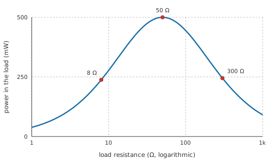
The curve those three points sit on is a blunt one. Two errors in opposite directions, one a factor of six down and the other a factor of six up, give away nearly the same half of the available power, which the logarithmic axis makes plain. Whether half is a disaster or a rounding error depends on where the signal came from. Off an antenna it is the difference between hearing a station and not; out of a bench generator it is a knob you turn. The arithmetic does not settle whether a matching network gets fitted, and that judgement does.
Engineer
What a mismatch costs
Delivered power against available power collapses into something compact. The load's power is the source voltage squared times the load resistance, over the square of the two resistances added; divide by the available power and the voltage disappears, leaving four times the product of the two resistances over the square of their sum. Only the ratio of load to source survives. A load six times too small and one six times too large therefore land within a hair of each other, as the figure showed.
Radio practice writes the same information a different way. The reflection coefficient is the load minus the reference resistance, divided by their sum. It runs from minus one at a short circuit, through zero at a perfect match, to plus one at an open circuit, and the fraction of power that gets through is one minus its square. Putting delivered power against available power as a ratio in decibels turns that fraction into the figure people quote:
Worked example — The same mismatch counted as a reflection
Against the 50 Ω source, the 8.0 Ω load has a reflection coefficient of -0.724, negative because the load is the smaller of the pair.
One minus the square of that number is the fraction that reaches the load, and it returns 47.6 %, the figure the divider already gave. As a power ratio in decibels the shortfall is -3.23 dB, the mismatch loss.
Two more numbers describe the same reflection. The return loss, incident amplitude measured against reflected, is 2.80 dB. Had that load terminated a fifty-ohm line instead of sitting on the source's terminals, the standing wave ratio on the line would be 6.25.
Everything so far has been resistive on both sides. Real sources carry reactance, and then equal magnitudes are no longer enough. Take a source of resistance with series inductive reactance, and give it a load of the same resistance with an equal capacitive reactance. The two reactances point in opposite directions on the phasor diagram and cancel, the loop is left purely resistive, current and voltage come back into step, and the load collects the full available power. That is the conjugate match: same resistive part, opposite sign of reactance.
Leaving the reactance in place has a price, and it is a measurable one.
Worked example — A reactive source driven by a plain resistor
Add 30 Ω of series reactance to the 50 Ω source and put a resistive load of the same value across it. The two resistances come to 100 Ω, the reactance survives untouched, and the loop presents 104.4 Ω instead.
Current falls to 95.78 mA and the load receives 458.7 mW, or 91.7 % of what the source could have given.
Cancel the reactance with an equal and opposite one and the loop carries 100 mA, handing over the whole 500 mW.
The result is narrower than its confident arithmetic suggests, and the boundaries are worth stating. Reactance is a function of frequency, so a conjugate match is exact at the frequency it was computed for and slides off either side of it. Where either impedance is complex the reflection coefficient is complex too, and it is the magnitude that the power fraction uses. Standing wave ratio describes a wave travelling on a line: a load bolted to a source through a short wire has no standing wave, and borrowing the term there imports a picture that is not present. The account also assumes a linear source whose equivalent resistance holds still, observed in the steady state, so an output stage that clips or a source whose resistance moves with drive level is matched at one operating point and mismatched at the next.
Professional
The price of a matching network
What the gearbox is made of
A transformer is the broadest instrument in the set, and even it has two edges. Magnetising inductance runs out at the bottom of the band and leakage inductance with winding capacitance closes it off at the top, while copper resistance and core loss take a share of everything in between. Transformers as components covers the selection.
Below that, the workhorse is the L-network: one series reactance and one shunt reactance, sized to rotate the load impedance onto the source's value. It is cheap and it is exact at a single frequency. The higher the impedance ratio it has to bridge, the higher the loaded Q it develops and the narrower the band it holds; adding a third element buys back some control over that bandwidth. Above a few hundred megahertz the same job is done with lengths of line, quarter-wave sections and stubs, since a length of cable is easier to make accurately than an inductor is.
There is a ceiling on how well any of it can work. A load that stores energy sets a limit on how good a match a lossless network can hold across a band, a result usually named after Bode and Fano. A good match over a narrow band or a mediocre one over a wide band is a choice; both at once is not on offer.
When the network costs more than the mismatch
Worked example — A load close enough to leave alone
Put 75 Ω across the same 50 Ω source. The load holds 6.0 V and takes 480 mW, the reflection coefficient is 0.200, and on a line that would read as a standing wave ratio of 1.50. The mismatch is costing -0.18 dB.
A small network with an insertion loss of 0.50 dB would take out more than the mismatch does, so fitting one here makes the link worse.
The 8.0 Ω load is a different case. The same network recovers 2.73 dB of the -3.23 dB that mismatch was taking, which is worth having.
Work the mismatch out in decibels before reaching for a network, and compare it against the loss of the thing you were about to add. The comparison also decides how much precision the network deserves: a match good to a few per cent and one good to a fraction of a per cent differ by a quantity no instrument in the signal path will resolve.
The other reason to terminate a line
On a transmission line the reflected wave is a problem in its own right, before anybody counts watts. A fast digital edge that meets a wrong termination comes back along the line and adds to the next edge, producing overshoot and ringing at the receiver. Terminating a line in its characteristic impedance stops that, and the aim there is a clean waveform, not the largest possible power. The fifty or seventy-five ohms marked on a connector is a property of the cable's geometry, and not something an ohmmeter finds between its ends.
Where matching is the wrong target
Line-level audio and instrumentation deliberately do not match. A source with a low output impedance feeding an input with a high one, an arrangement called voltage bridging, transfers nearly the whole voltage and loads the source hardly at all, which is what a voltage follower exists to provide. The six-hundred-ohm convention still printed on older equipment came from telephone lines, where the cable really did behave as a line, and it stopped being a requirement once amplifiers became stiff.
A power amplifier is not conjugate matched to its speaker either. Its output impedance is a few milliohms against a load of several ohms, and the ratio between them is quoted as damping factor. Inside the output stage the load a transistor sees is chosen by load line rather than by conjugate match: the resistance that lets the device swing its full available voltage and current inside its ratings, which is a different question with a different answer.
Low-noise design pulls in a third direction again. The source impedance that gives a stage its lowest noise figure is generally not the one that gives it the most gain, so a receiver's first stage is designed around noise and the mismatch that comes with it, and later stages tidy up. Matching is one objective among several, and the interesting work is deciding which of them this particular interface is for.
Common mistakes
- Matching a supply to what it feeds — a regulator or a battery run at its matched load turns half of everything it produces into heat inside itself. Match where the source resistance is fixed and the power is scarce; keep everything else stiff and unmatched.
- Reading a turns ratio as an impedance ratio — turns go as the square root. Changing an impedance by four needs two turns to one, not four.
- Fitting a network for a mismatch smaller than the network's own loss. Put the mismatch loss and the insertion loss side by side in decibels first; sometimes the answer is a piece of wire.
- Matching the magnitudes and ignoring the sign of the angle — two impedances of equal magnitude with reactance the same way round leave that reactance in the loop. A conjugate reverses the sign, and that reversal is what cancels it.
- Quoting a standing wave ratio for a lumped circuit. The number describes a wave on a line; with no line there is nothing standing and nothing to measure.
- Assuming one calculation covers the band — every reactive matching network is exact at a single frequency. Check the band edges, since that is where the design will be judged.
Frequently asked questions
What does impedance matching do?
It transforms a load so the source sees its own impedance looking back, which is the condition under which the source gives up the most power it can. A transformer or a set of reactive components does the transforming, and neither consumes power, so what changes is the ratio and not the amount of energy in play.
Why is a matched system only fifty per cent efficient?
At the matched point the source's internal resistance and the load are equal and carry the same current, so they dissipate equally. Half the energy the source produces never leaves it. That is acceptable where the alternative is collecting less of a small signal, and unacceptable anywhere the job is to move energy.
What is the difference between a conjugate match and matching to fifty ohms?
A conjugate match cancels the source's reactance as well as equalling its resistance, and it is the condition for maximum power from that particular source. Matching to a stated reference such as fifty ohms is about the line between the two ends: it stops the line reflecting, whatever the source behind it happens to be doing.
Where does the power go when a load is mismatched?
On a transmission line the part that is not accepted travels back towards the source as a reflected wave. With a load sitting directly on a source's terminals nothing is reflected anywhere; the source simply never delivers that power, and draws less from whatever supplies it.
Should I match a modern audio amplifier to its loudspeaker?
No. Amplifier outputs are built with the lowest impedance the design allows, several hundred times below the speaker, so nearly the whole voltage reaches the coil and the amplifier keeps control of the cone. Matching would halve the power available and heat the output stage for nothing.