
Quick Answer
Capacitive reactance is the opposition a capacitor offers to an alternating current, written X_C and measured in ohms. It equals one divided by two pi times the frequency times the capacitance, so it falls as either of those rises. Unlike resistance, reactance stores energy and hands it back instead of turning it into heat.
Intuition
Opposition that depends on how fast the voltage swings
A capacitor stores charge, and the capacitance lesson said how much: so many coulombs for every volt across it. Nothing in that number mentions time. Reactance is what appears once time is brought in.
Put a steady voltage on a capacitor and, after the charge has settled, nothing moves. No current flows, and to the rest of the circuit the part looks like a break in the wire. Now make the voltage swing up and down instead. Each swing has to push charge onto the plates and then pull it off again, and charge moving along a wire is a current. How big that current gets depends on how quickly the swings arrive. A slow swing gives the charge plenty of time to make the trip, so the current is small. Speed the swinging up and the same charge has to make the same trip in less time, which means more of it flows per second.
More current for the same voltage is what easier passage means. A capacitor therefore obstructs a slow signal heavily and a fast one hardly at all, and the quantity that measures the obstruction is capacitive reactance. It is quoted in ohms, the same unit as resistance, because it does the same job of relating volts to amperes.
The shared unit is where the resemblance stops. A resistor turns the energy it takes into heat. A capacitor accepts energy during one part of the cycle and hands all of it back during the next, so it stays cool however many ohms of reactance it happens to present.
Practitioner
One capacitor across three decades
Frequency in hertz and capacitance in farads give ohms straight out, with no constant to remember beyond the two pi. Both quantities sit in the denominator and both behave the same way: double either one and the reactance halves. Convert to plain hertz and plain farads before dividing, because a nanofarad entered as a microfarad moves the answer by a factor of a thousand and the result still looks plausible.
Worked example — One part, three frequencies
The same capacitor, unchanged, read at a mains frequency, an audio frequency and a low radio frequency. At 50 Hz it presents 14.47 kΩ. At 1.0 kHz the figure is 723.4 Ω, and at 100 kHz it comes to 7.234 Ω.
One part with one marked value, 220 nF, spans more than three decades of opposition across that range. The last two figures share their digits because a hundredfold rise in frequency is a hundredfold fall in reactance and nothing more.
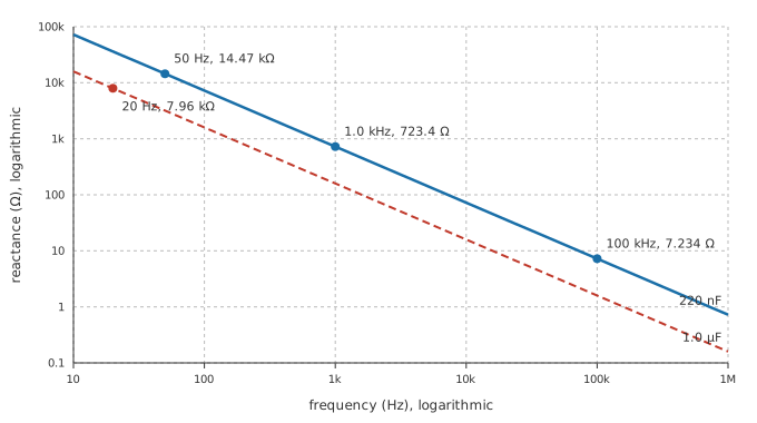
On logarithmic axes the relationship is a straight line falling one decade of reactance for every decade of frequency, and a capacitor of a different value gives a parallel line offset from the first. Reading a value off a plot like that is usually quicker than doing the division, and it puts the ordering in plain sight: the bigger capacitor sits below the smaller one at every frequency on the axis.
A reactance on its own decides nothing. The number only means something beside the resistance working with it, since between them they form a divider.
Worked example — Sizing a coupling capacitor by comparison
An audio stage passes its signal on through a series capacitor of 1.0 µF. At the bottom of the audible range, 20 Hz, that capacitor presents 7.96 kΩ.
Whether that counts as small depends entirely on the input resistance of the stage being fed. Against an input of a few hundred kilohms it is a minor obstruction and the bass survives intact. Against an input of a few kilohms it is comparable to the load, and the lowest notes are already being lost before anything else in the design has had a say.
Both ends of the expression are worth carrying around. At DC the frequency is zero, the reactance is unbounded, and the capacitor is an open circuit; DC blocking is nothing more than that fact put to work. Push the frequency high enough and the reactance shrinks towards nothing, so the capacitor looks close to a short, which is what decoupling and bypass capacitors rely on. Everything the low-pass and high-pass filter lessons do with an RC pair is this same comparison, worked out across a whole range of frequencies at once.
On the bench an LCR meter will report reactance as well as capacitance, and it always states the test frequency it used, since a reactance quoted without one says nothing.
Engineer
The current that arrives a quarter cycle early
Current into a capacitor is set by how fast its voltage is changing, not by how large that voltage is. The capacitance lesson wrote that as i = C·dv/dt. Feed the part a sine wave and the derivative of a sine is a cosine at the same frequency, scaled by the rate at which the angle advances. The current is therefore also a sinusoid; its peak is the capacitance multiplied by that rate and by the peak voltage; and the ratio of peak voltage to peak current lands on one divided by the rate times the capacitance. That ratio is the reactance. The rate in question is the angular frequency:
Substituting two pi f for it recovers the working form from the layer above and accounts for the two pi sitting in it. The two pi is not a fitted constant; it is the count of radians in one turn.
Worked example — Peak current into the same part
Drive the same capacitor at 1.0 kHz, where its reactance is 723.4 Ω, from a source whose peak is 3.0 V. The angular frequency is 6283.2 rad/s, and peak voltage over reactance puts the peak current at 4.15 mA.
That current is largest as the voltage passes through zero, since that is where the voltage climbs fastest, and it falls to nothing at the voltage peaks, where the waveform is momentarily flat.
A cosine is a sine advanced by a quarter turn, so the current reaches its peak a quarter of a cycle before the voltage reaches its own. The capacitor's current leads its voltage. Stated as a delay instead of an angle, that lead is a fixed fraction of the period and so shrinks as the frequency climbs:
Worked example — A quarter cycle, in time and in degrees
One cycle at 1.0 kHz lasts 1.0 ms, so a quarter of it is 250 µs. Turned into an angle, that quarter is 90°.
The angle stays put at every frequency. The delay does not: at a hundred times the frequency, the same quarter cycle occupies a hundredth of the time.
Which way that quarter cycle runs separates a capacitor from an inductor, where the current lags the voltage by the same quarter cycle and the reactance climbs with frequency instead of falling. The quarter cycle is also what stops a reactance from dissipating anything. Instantaneous power is voltage times current, and with the two a quarter cycle apart that product spends as much of the cycle negative as positive. Energy flows into the capacitor and back out again in equal measure, so the average over a whole cycle is zero. In a resistor the voltage and current stay in step, their product is never negative, and the energy only ever travels one way.
The model carries conditions, and they are easy to leave unsaid. It describes a steady sinusoid at a single frequency, because the derivative behaves this tidily only for a sine: a square or triangular wave has to be broken into its harmonics first, with each component given its own reactance. The circuit also has to have settled, so nothing here applies during the first instants after a switch closes, which is the transient territory of the RC time constant. Reactance is a magnitude and no more than that: it fixes the size of the ratio between voltage and current, never the angle between them, and that angle has to be carried along separately until impedance folds the two back into one quantity.
Professional
When the calculated ohms are not the ohms you get
All the arithmetic here started from a capacitance, so it inherits whatever is wrong with that capacitance. On a class 2 ceramic the marked value is a starting point and not a measurement: temperature moves it, ageing moves it, and applied DC bias moves it a long way.
Worked example — What bias derating does to the answer
Take a part marked 220 nF that measures 120 nF at its working bias, an illustrative loss rather than a catalogue figure. At 1.0 kHz its reactance is no longer 723.4 Ω but 1.33 kΩ.
No component was swapped and no corner frequency was recalculated, and yet the divider this capacitor sits in has been retuned by nearly a factor of two.
A capacitor is also more than a capacitance. Its plates and terminations contribute a small series resistance, its leads and internal current path contribute a small series inductance, and the three together make a series RLC circuit the part cannot escape. That combination has a resonance:
Above it the inductive reactance, which climbs with frequency, has overtaken the capacitive reactance, which falls. What the surrounding circuit meets is the difference between the two, taken before the series resistance is brought in:
Worked example — The frequency above which the part behaves as an inductor
Give the same capacitor an equivalent series inductance of 5.0 nH and a series resistance of 20 mΩ, both illustrative example parameters and not catalogue values. The pair resonates at 30.15 Mrad/s, which is 4.80 MHz once radians per second are converted to hertz.
At 10 MHz, well past that point, the capacitive reactance has fallen to 72.34 mΩ while the inductive reactance has climbed to 314 mΩ. The magnitude the circuit sees is 243 mΩ.
The ideal calculation promised 72.34 mΩ at that frequency and the real part delivers several times as much, and the size of that gap is what self-resonance costs in practice. Fitting a larger capacitance will not close it, since capacitance is no longer the quantity being measured; shorter leads and a smaller package will. Supply rails therefore carry a mixture of decoupling capacitor sizes and packages instead of one large part, and ESR and capacitor parasitics takes that argument further.
Loss is the other departure from the ideal, and it is where the claim that a reactance stays cool has to be qualified. A pure reactance dissipates nothing, but no real capacitor is a pure reactance: its series resistance turns ripple current into heat inside the part, and real dielectrics absorb a small amount of energy on every cycle as their molecules are dragged back and forth. Manufacturers quote the combined effect as a dissipation factor or as its reciprocal, and it sets the ripple current a smoothing capacitor may be asked to carry.
Choosing a part by its reactance alone goes wrong in a predictable order, so the checks are worth running in the same order every time. Work out the reactance needed at the frequency that matters. Confirm the part still holds that capacitance at the bias and the temperature it will meet in service. Put its self-resonance comfortably above the highest frequency in the signal. Then look at the ripple current it will carry against what the part is rated for. A film capacitor keeps its value where a class 2 ceramic will not, and the price of that stability is size.
Common mistakes
- Leaving the prefixes in the division — nanofarads and kilohertz happen to cancel often enough to breed confidence. Convert to farads and hertz first, then sanity-check the order of magnitude against a plot.
- Adding a reactance to a resistance arithmetically — a kilohm of reactance in series with a kilohm of resistance does not make two kilohms. They sit a quarter cycle apart and combine as the sides of a right triangle.
- Quoting a reactance with no frequency attached — the same part has a different reactance at every frequency, so the number alone carries no information.
- Expecting a capacitor to look like a short at any high frequency — past its self-resonance the lead inductance takes over and the opposition climbs again.
- Treating a reactive ohm as a dissipating ohm — reactance produces no heat; the series resistance and the dielectric loss beside it do, and those are what the ripple rating is about.
- Calculating with the marked capacitance — tolerance, temperature and DC bias all move the real value, and class 2 ceramics move it furthest of all.
Frequently asked questions
What is capacitive reactance?
The opposition a capacitor offers to an alternating current, measured in ohms. It equals one divided by two pi times the frequency times the capacitance, so a larger capacitor and a higher frequency both reduce it.
Why does reactance fall as frequency rises?
Each cycle moves the same quantity of charge on and off the plates. A shorter cycle means that charge has to move in less time, which is more current, and more current for the same applied voltage is less opposition.
Is reactance just resistance by another name?
They share the ohm and both relate a voltage to a current, and the resemblance ends there. A resistance consumes the energy it takes; a reactance stores it and returns it, and it shifts the current a quarter cycle relative to the voltage.
Does a capacitor pass DC?
No. At zero frequency the reactance is unbounded, so once the charge has settled the capacitor is an open circuit. Only a changing voltage keeps current moving on and off the plates.
How do I pick a coupling capacitor?
Compare its reactance at the lowest frequency you need to pass against the resistance it feeds. Reactance well below that resistance lets the signal through almost untouched; reactance comparable to it means the low end is being attenuated.
Why does a capacitor stop working at high frequency?
Its lead and internal inductance resonate with its own capacitance. Above that self-resonant frequency the inductance dominates, and the part's opposition rises with frequency instead of falling.