
Quick Answer
A passive high-pass filter is a capacitor in the signal path with a resistor from the output down to ground. Frequencies above its cutoff reach the output almost unchanged, while below the cutoff the output falls by twenty decibels for every tenfold drop in frequency. The corner sits at one over two pi R C.
Intuition
Only the changes get through
Swap the two parts of a low-pass section and the filter turns round. The capacitor moves into the signal path, the resistor runs from the output down to ground, and the half of the signal that used to survive is now the half that does not.
A capacitor passes nothing steady. Hold a fixed voltage on one side of it and current flows only while the charge settles; once settled, no current crosses it, the resistor below has nothing to carry, and the output rests at zero. Change the input and charge has to shuffle to keep up. That shuffling is a current, the current runs down through the resistor, and the voltage it develops there is the output. Faster changes move more charge, so more of the input reaches the far end.
The output therefore follows what the input is doing, not what it is sitting at. A slow drift looks almost like a fixed voltage to a capacitor and gets removed almost as thoroughly. Between the slow signals that vanish and the quick ones that pass unharmed lies the cutoff frequency, and nothing snaps shut there either. The output climbs a smooth slope, and ten times above the corner it has all but arrived.
Most sections built this way are not there to shape tone. Their job is to stop a steady voltage in one stage from reaching the next, and a capacitor doing that job is usually called a coupling capacitor. The filtering comes along with it whether or not anyone wanted it.
Practitioner
Placing the corner under the band
An RC high-pass section is a voltage divider whose upper arm shrinks as the signal speeds up. The capacitor is that arm: down low it dominates the pair and keeps the input for itself, up high it is barely in the way and the resistor takes almost everything.
A low-pass section built from the same two parts corners at the same frequency. Only the component the output is taken across differs, and it decides which side of the corner survives.
Capacitive reactance is the part of the circuit that moves. The resistor holds still while the capacitor's opposition falls in inverse proportion to frequency, and where the two are equal is where the corner sits.
In a coupling application the resistor is rarely a free choice: it is whatever the following stage presents at its input, or a bias resistor defining the output's DC level. That leaves the capacitance, rounded up to a stocked part and never down, since a low corner costs nothing and a high one eats into the band.
Worked example — A 1.0 µF capacitor into 10 kΩ
With 1.0 µF in the signal path and 10 kΩ from the output down to ground, the corner falls at 15.9 Hz.
The capacitor's reactance there is 10 kΩ, matching the resistor. The corner is the one frequency at which the two arms oppose the signal equally, and the output there is 0.707 of the input, or -3.01 dB.
How much survives at any other frequency depends on how that frequency compares with the corner:
The ratio appears twice, on top and under the root, and that extra copy on top is what distinguishes this form from the low-pass one: as frequency falls the numerator collapses and takes the gain with it. Responses are quoted in decibels far more often than as a plain ratio, and a gain is a ratio of two voltages:
Worked example — Three points across the bottom of the audio band
At 5.0 Hz, well under the corner, only 0.300 of the input survives, a loss of -10.47 dB.
At 20 Hz, the conventional bottom of the audio band, the output has recovered to 0.782, or -2.13 dB — more loss than a design aiming at a flat response would accept.
By 100 Hz the section has stopped doing anything worth measuring: 0.988 of the input, which is -0.11 dB.
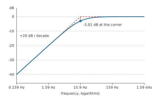
Below the corner each tenfold drop in frequency costs another factor of ten in amplitude. A decade under it, at 1.59 Hz, the output is down to 0.0995, or -20.04 dB, and the loss goes on growing at that rate down to a steady voltage, where it is total. Rising at twenty decibels per decade below the corner, flat above it, bending through the middle: sketching a response from a corner and a slope is what a Bode plot formalises.
Sections like this sit between almost every pair of amplifier stages, keeping one stage's operating point out of the next one's input, and they strip a sensor's standing offset off a small signal before it meets a gain stage. The AC coupling switch on an oscilloscope input is the same circuit, with its corner given in the manual.
Finding that corner on the bench takes a function generator and a two-channel scope: sweep down from well above the cutoff until the output reaches seven tenths of its passband amplitude. Keep the second channel on the input while sweeping, since this section's input impedance climbs as the frequency falls and a generator with output resistance of its own will sag into it.
Engineer
Magnitude and the angle that comes with it
Combining the two arms is not a matter of adding two numbers. Current into a capacitor runs a quarter cycle ahead of the voltage that appears across it, so the capacitor's drop and the resistor's drop reach their peaks at different instants. What they add up to is the root of the sum of their squares, and that total is the series impedance of the pair:
An RC section holds no inductance, so the inductive term drops out and what remains is the root of R squared plus X_C squared. The gain magnitude is the share of that total which the resistor holds: its resistance divided by the impedance magnitude of the two together. For the low-pass the numerator was the reactance; here it is the resistance, and every other line of the algebra is identical.
Worked example — The divider route against the gain expression
Take the same section at 10 Hz, comfortably below its corner. The capacitor's reactance there has grown to 15.92 kΩ, and worked against the resistor that gives an impedance magnitude of 18.80 kΩ.
The resistor's share of it is 0.532. Feed the same frequency and the same corner into the gain expression instead and the answer is 0.532, which is -5.48 dB.
One piece of algebra, written twice. Divide the top and the bottom of the divider ratio by the resistance, substitute the reactance expression, and the ratio of frequency to corner frequency is what is left. The square root carries the quarter-cycle offset between the two drops and nothing more.
Magnitude describes only half of what the section does. The output also leads the input, by an angle whose tangent is the corner frequency divided by the signal frequency, so the lead is a quarter cycle far below the corner and vanishes far above it. At the corner it is 45.0°, halfway between the two limits. Down at 10 Hz it has grown to 57.86°.
The angle reaches much further from the corner than the attenuation does, and that asymmetry decides where a coupling corner belongs. At 20 Hz this section is barely two decibels down while the phase has already turned by 38.51°. A single stage can absorb that. Three cascaded stages each contributing something similar will not, and a feedback loop that has to stay stable counts every degree.
The model has edges worth naming before the next layer leans on it. It describes one pole, and a network with two independent reactive components has a different shape that can rise above its passband level before it settles, which a single RC never does. It assumes a steady sinusoid held long enough for the transient to die out, so it says nothing about what the section does to an edge: fed a square wave, this circuit passes the transitions and lets the flat parts sag back towards zero, a droop governed by the same product of R and C that the RC time constant describes and that pulse response works through. The parts are taken as linear and constant, which a capacitor whose value shifts with the voltage across it is not. An ideal source and an unloaded output are assumed, and both assumptions come apart below. The straight lines on the figure are approximations as well: the rising asymptote and the flat one meet three decibels above where the response passes, and they stay optimistic for about a decade in each direction.
Professional
What a coupling capacitor has to survive
Source, load and the corner they move
The R in the corner expression is the whole resistance the capacitor charges and discharges through, looking out from its own two terminals. It is a Thévenin resistance, and the marked resistor is one contributor to it.
Source resistance joins the series path and drags the corner down, which sounds harmless until the second effect shows up: well above the corner the capacitor is effectively a short, and the source resistance then works against the shunt resistor as a plain divider that costs amplitude at every frequency the section passes.
Worked example — The same section behind a real source
Drive it from a source with 600 Ω of output resistance and the series path becomes 10.6 kΩ, putting the corner at 15.0 Hz.
Up in the passband the same two resistances divide on their own: 1.0 V going in leaves 0.943 V at the output, a flat loss of -0.51 dB.
A load works the other way round. Anything hung from the output to ground sits in parallel with the shunt resistor, lowers the resistance the capacitor works into, and pushes the corner up.
Worked example — A following stage across the shunt arm
Connect a stage with 22 kΩ of input resistance. In parallel with the shunt resistor that gives 6.875 kΩ, and the corner climbs to 23.15 Hz.
To hold the original corner against that lower resistance the capacitance has to rise in the same proportion, to 1.45 µF, so the nearest stocked part above it goes in.
Here the two circuits part company. Loading a low-pass costs passband amplitude as well as corner accuracy; loading a high-pass fed from a stiff source costs only the corner, because the output is taken across the very resistance the load is shunting. That makes the high-pass the more forgiving of the two to load, and the less forgiving to a source with resistance of its own.
Choosing the capacitor
A capacitance of this order at audio frequencies is an aluminium electrolytic or a film part, and size and price are the smaller half of the decision. A coupling capacitor spends its whole life with a steady voltage across it, so a polarised electrolytic has to be fitted the right way round and the DC across it must keep that sign through power-up, power-down and any fault the stage can reach. Where the polarity can reverse, the part has to be non-polar or film.
Electrolytics also hold their value loosely and lose it as they age and dry out, so a corner set with one is a nominal figure that migrates upward over years. Film parts are stable and get chosen wherever the corner has to stay put. Class 2 ceramics are the wrong answer twice over: their capacitance falls under DC bias, and a coupling capacitor always has bias across it, so the corner lands higher than the calculation said and moves with temperature besides. A capacitance that varies with the signal voltage riding on that bias also distorts the signal it is meant to be passing. Where the dielectric is chosen deliberately, none of this is a surprise.
Leakage does its damage somewhere else. Real capacitors pass a small DC current, that current flows through the shunt resistor, and a DC offset appears at the output of a circuit whose entire purpose was to have none. High shunt resistances make the offset larger, and electrolytics leak far more than film parts do.
The corner at the other end
The passband does not run on forever. Stray capacitance at the output node, from the wiring and from whatever the section feeds, works against the source and shunt resistances in parallel and forms a low-pass corner above the intended band.
Worked example — Where the passband stops
Take 100 pF across the output, a stand-in for a short run of wiring and a following input, not a catalogue value. The source and shunt resistances in parallel come to 566 Ω, and the two together corner at 2.81 MHz.
That makes any real high-pass a band-pass with a very wide band, and on a low-impedance audio stage the upper corner sits far enough out to ignore. Raise the resistances to get a low corner without a bulky capacitor and the upper corner comes down to meet the band, the section starts collecting noise from its own resistance, and the high-value node makes a serviceable aerial for anything radiating nearby.
Two sections in cascade double the slope below the corner and move the corner as well. Each one is three decibels down at its own cutoff, so a buffered pair is six decibels down there and the pair's own cutoff has slipped above either section's. Unbuffered, the second section is simply the load discussed above and both corners shift. Sharper transitions than a cascade of RC poles can give come from an active filter, where an amplifier between the sections buys a response that peaks before it falls. Once several poles are being placed on purpose, the response gets written as a transfer function and the poles are positioned in that form instead of one section at a time.
Common mistakes
- Putting the corner at the lowest wanted frequency — the section is three decibels down at its own corner and has already turned the phase by an eighth of a cycle. Place the corner well below the band, then check what the phase is doing at the bottom of it.
- Treating the shunt resistor as a component you chose — in a coupling stage it is the following input resistance, in parallel with any bias resistor, and the marked part may not even be there. Work out what the capacitor really sees before picking its value.
- Reaching for a class 2 ceramic — a coupling capacitor always has DC across it, and class 2 dielectrics lose capacitance under bias, so the corner arrives higher than the calculation promised and drifts with temperature.
- Fitting a polarised electrolytic where the DC can reverse — the polarity has to hold through power-up and power-down, not just in normal operation. Use a non-polar or film part where it might not.
- Sketching from the asymptotes and stopping there — the two straight lines cross three decibels above where the response passes, and they stay optimistic for about a decade on either side of the corner.
- Assuming the passband has no upper end — stray capacitance at the output and resistance at the source close the band from above, and a high-impedance section closes it sooner than most people expect.
Frequently asked questions
Is a coupling capacitor the same thing as a high-pass filter?
In circuit terms, yes. A coupling capacitor sits in series with the signal and the following stage's input resistance completes the pair, so the two together form the section described here. The names differ only in intent: one is drawn to block a DC level, the other to shape a response, and both do both.
Why does a high-pass section block DC completely?
No steady current can cross a capacitor's dielectric. With nothing flowing, the shunt resistor develops no voltage, so whatever fixed level the input sits at produces exactly zero at the output. A real capacitor leaks slightly, which puts a small offset there instead of none.
Will a larger capacitor keep more of the low end?
It moves the corner down and leaves the slope untouched, so yes for the frequencies between the old corner and the new one. The slope belongs to the number of poles and not to the component values, so a bigger part buys reach rather than sharpness.
Why does the output lead the input instead of lagging it?
The output is the voltage across the resistor, which follows the current, and the current into a capacitor peaks a quarter cycle before the voltage across it does. The lead runs from a quarter cycle far below the corner down to nothing far above it, passing through half of that at the corner itself.
How far below the wanted band should the corner sit?
Far enough that the phase shift at the lowest wanted frequency is tolerable, which is a stricter test than amplitude and gets stricter still when several stages each add their own. Work the phase out at the bottom of the band, add up the contributions of every coupling stage in the chain, and set the corners from that total.