
Quick Answer
A voltage divider is two resistances in series across a source, with the output taken at the junction between them. That output is the source voltage multiplied by the lower resistance over the sum of both, so the ratio of the two arms sets it. Drawing any current from the tap pulls it below that figure.
Intuition
Reading the voltage at the junction
A single resistor across a supply has the whole supply across it. Put a second one in the chain and the supply gets shared out between them, so the junction where the two meet sits somewhere between the top rail and the bottom. Which two resistances you pick decides where.
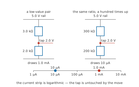
A chain of 3.0 kΩ and 2.0 kΩ across 5.0 V is a single path, so one current flows in both parts of it: 1.0 mA. Each resistor's drop is that shared current through its own resistance, which puts 3.0 V across the upper one and 2.0 V across the lower, and the two together account for the supply.
Clip a meter's black lead to the bottom of the chain and touch the red lead to the junction. It reads 2.0 V, since the lower resistor's drop is the only thing standing between the two probes. That reading is the divider's output, and the junction is called the tap.
The split came out of that shared current. Each arm took a share of the supply in the same proportion as its own resistance: three fifths above, two fifths below. Make the arms equal and the tap sits at half the supply; make the lower one a ninth the size of the upper and it sits at a tenth. All of this is Ohm's law applied twice along a series chain, and the fraction is settled the moment the two values are chosen.
Practitioner
Choosing a pair of values
R_2 is the arm between the tap and the reference, R_1 the arm between the tap and the source. Both appear in the denominator and only one of them in the numerator, so the result is always a proper fraction of the input, and a resistive divider therefore attenuates whatever pair of values it is built from.
The expression responds to the proportion of the two resistances and not to their size. Multiply both arms of the chain above by a hundred, to 300 kΩ and 200 kΩ, and the tap stays at 2.0 V. What moved is the current the chain draws, from 1.0 mA down to 10 µA. So the ratio and the absolute level get settled on separate grounds: the wanted output dictates the ratio, while the level is left entirely open by the expression above. Choosing it is a job of its own, and it comes up again at the end of this lesson.
Work backwards from a wanted output and the requirement fixes only R_1 ⁄ R_2 = (V_in − V_out) ⁄ V_out, which leaves one arm free. Fix one at a convenient value, let the other follow, then round both to stocked E-series values and recompute what the tap will really sit at. The current in the chain is the same in both arms and comes from Ohm's law over their sum:
Worked example — Designing to a wanted tap voltage
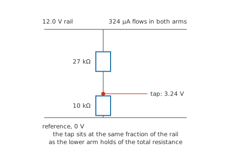
The requirement is a tap at 3.30 V taken from a rail of 12.0 V, feeding an input that draws nothing measurable.
That requirement reaches only as far as the ratio. R_1 ⁄ R_2 = (V_in − V_out) ⁄ V_out = 2.64, so fixing the lower arm at 10 kΩ asks for an upper arm of 26.4 kΩ — a value nobody stocks. The nearest E24 step is 27 kΩ. Put that back through the divider expression instead of hoping, and the tap sits at 3.24 V, low by 1.7 %. The pair draws 324 µA from the rail, continuously.
The error is the granularity of the resistor series arriving in the ratio, and a third resistor added somewhere will not improve it. The ways out are a tighter series, a trimmer, or accepting the number and correcting for it in software.
That 3.24 V is the reading with nothing connected to the tap, a condition the arithmetic above assumes throughout.
Dividers turn up wherever a level has to be scaled down and nothing has to be driven. That covers a rail brought inside a converter's input range, the feedback network that tells a regulator what output to hold, the base bias of a transistor stage, the reference arms of a Wheatstone bridge and the fixed attenuators in a signal path. A potentiometer is the same circuit with the tap made movable along one resistive track.
Engineer
Loading the tap
The ratio has a short derivation behind it. The two arms are the only elements in one loop, so they carry one current, I = V_in ⁄ (R_1 + R_2), and the tap voltage is whatever the lower arm drops at that current, V_out = I × R_2. Substitute the first into the second and the current cancels, leaving V_out = V_in × R_2 ⁄ (R_1 + R_2). Any dependence on the absolute values goes out with it.
The cancellation holds only while both arms carry the same current. Connect anything from the tap to the reference and the lower arm stops doing so. The load and the lower arm share both of their nodes, which makes them a parallel pair, and the divider that is really present has that combination as its lower arm.
Worked example — The same tap under a heavy load and a light one
Keep the divider designed above: 27 kΩ above 10 kΩ across 12.0 V, tap at 3.24 V unloaded.
Connect 10 kΩ from tap to reference. That resistance and the lower arm combine to 5.0 kΩ, and the divider formed by the unchanged upper arm against that combination puts the tap at 1.875 V, down by 42 %. The divider is doing its arithmetic correctly, on the lower arm it now actually has.
Swap the load for 1.0 MΩ. The combination becomes 9.90 kΩ, barely moved from the arm's own value, and the tap reads 3.22 V, low by 0.72 %.
Both figures assume a load that is a plain resistance and holds still. An amplifier input whose resistance shifts with signal level, a switched input that connects and disconnects, or a second divider hung on the same tap will move the output by amounts that change while the circuit runs, and the divider passes that movement on to whatever it feeds.
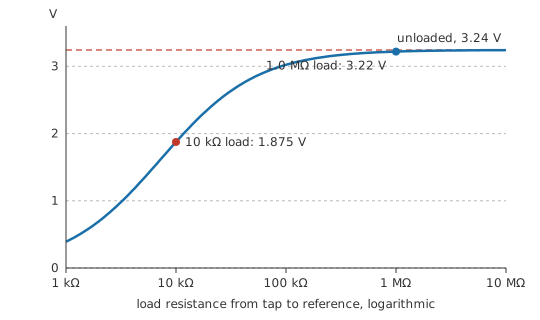
Recomputing a parallel combination for every load soon gets tedious, and there is a shorter route. Seen from the tap and the reference, the divider is a two-terminal network containing a source, and any linear network of that kind behaves at its terminals like one voltage source in series with one resistance, which is Thévenin's theorem. Both parts are easy to name here. The equivalent voltage is the unloaded tap voltage, 3.24 V. The equivalent resistance is what an ohmmeter between tap and reference would read with the source replaced by a short, which places the two arms in parallel: 7.30 kΩ.
The two numbers come from different places. The ratio produced the equivalent voltage, while the absolute values produced the equivalent resistance, which is always smaller than either arm on its own. A divider is therefore stiffer than its component values suggest, and never stiffer than its smaller arm.
Loading now becomes the same divider sum applied one level up: attach a load and the output is the equivalent voltage divided between the equivalent resistance and that load. A load ten times the equivalent resistance costs 9.1 % of the output, and a hundred times costs roughly a tenth of that. Check it against the heavy case above: 3.24 V behind 7.30 kΩ, loaded by 10 kΩ, returns 1.875 V, the figure the parallel-combination route already gave. Loading in general is this calculation, and a meter placed across a high-value divider is the case that catches people on a bench.
The equivalence comes with conditions. It holds for linear elements — resistances that do not change with the current through them — so a divider whose lower arm is a thermistor, an LED or a semiconductor input has no fixed equivalent resistance to quote. What it describes is the behaviour at those two terminals, so the currents in the individual arms and the power the divider dissipates are both lost to it. The statement is a DC one as well. The same argument run with impedances is what the Norton form and the AC treatment build on, and once stray capacitance across the arms enters it, the equivalent resistance becomes an equivalent impedance that falls as frequency rises.
Professional
Setting the absolute level
The requirement fixes the ratio and leaves the absolute values open, and that choice spans five or six decades with something to lose at each end of it.
Where to sit on the resistance scale
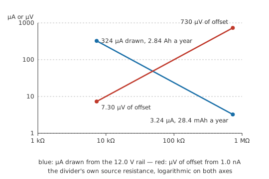
Low values spend current. The divider designed earlier draws 324 µA from the rail it monitors whenever the board is powered, read or not, which over a year is 2.84 Ah of charge, about an alkaline AA cell's worth. A hundredfold increase, to 2.7 MΩ over 1.0 MΩ, cuts that to 3.24 µA and 28.4 mAh.
The penalties run the other way. That same hundredfold raises the equivalent resistance to 730 kΩ, so loads that were negligible no longer are. An input bias current of 1.0 nA drawn through 730 kΩ generates 730 µV of offset belonging to the input stage — an error no calibration of the divider removes. A high-resistance node also picks up capacitively coupled interference more readily and contributes more thermal noise, and its stray capacitance becomes a real time constant.
Tens to a few hundred kilohms suits most rail monitoring on a mains-powered board. Battery designs push into megohms and pay for it with a buffer at the tap.
Ratio accuracy is a matching problem
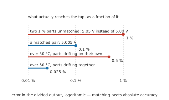
Accuracy in the ratio is a different purchase from accuracy in either resistor, so tight-tolerance parts are a weak way to buy it. Two 10 kΩ resistors of 1 % tolerance across 10.0 V nominally halve it to 5.00 V. Let them sit at opposite ends of their bands, 9.9 kΩ against 10.1 kΩ, and the tap moves to 5.05 V instead: both parts inside specification, the ratio out by the full tolerance of one of them.
A network built on one substrate is specified for the ratio between its elements as well as for their values, and 0.1 % on the ratio holds that same tap inside 5.005 V. Temperature works the same way: independent parts at 100 ppm/°C drift apart by up to 0.5 % over a 50 °C swing, while 5 ppm/°C of specified tracking holds the ratio to 0.025 %, as they share a substrate and a temperature. Matched pairs and divider networks are sold for that property, which is why resistor tolerance alone is the wrong specification to shop by here. Self-heating enters the same account, since the larger arm of an unequal divider runs hotter than its partner.
In front of a converter
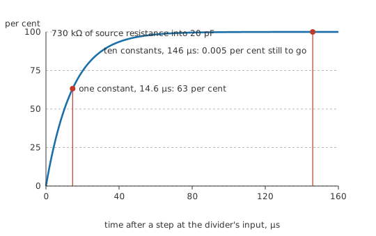
A divider ahead of an analog-to-digital converter has to settle as well as scale. A successive-approximation converter switches a sampling capacitor onto the pin for a fixed acquisition window and takes its charge from whatever drives it. Against an equivalent resistance of 730 kΩ and a node capacitance of 20 pF, the time constant is the product of the two:
That gives 14.6 µs, so a settled reading needs around 146 µs at ten time constants. Sample sooner and the converter reports a node still on its way, biased towards whatever the previous conversion left on the sampling capacitor; on a multiplexed input that looks like crosstalk between channels. The answers are a lower-impedance divider, a buffer at the tap, or a capacitor from tap to reference big enough to supply the sampling charge without moving much itself. The last is cheapest and slows the divider's response to real changes by the same time constant, which suits a rail monitor and not a fast shunt reading. Scope probes answer the AC version with a trimmer across the upper arm, adjusted until the capacitive ratio matches the resistive one at every frequency.
Feedback dividers and high-voltage strings
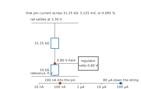
An adjustable regulator holds its feedback pin at an internal reference and lets a divider decide what output that corresponds to. A reference of 0.80 V with a lower arm of 10 kΩ asks for 31.25 kΩ above it to give 3.30 V, and the pair stands across the output and draws 80 µA whenever the regulator runs. That is quiescent consumption, which pushes low-power designs towards megohm feedback dividers and straight back into the bias-current problem: 100 nA drawn out of the feedback pin arrives through the upper arm, adding 3.125 mV to its drop and lifting the output by 0.095 %. Datasheets cap the recommended divider resistance on that account, and an adjustable regulator's output tolerance is mostly the divider's ratio tolerance. A zener shunt regulator is the same structure with a device in the lower arm.
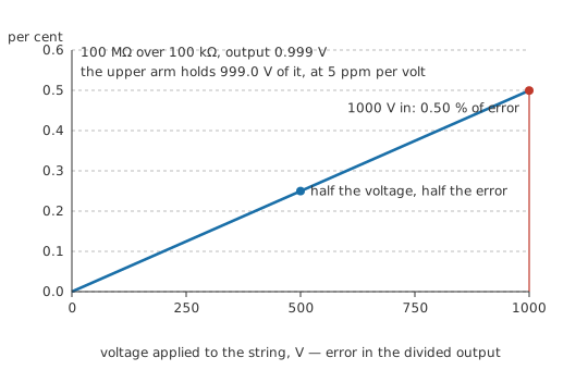
A divider measuring a kilovolt is limited by its insulation before its arithmetic. 100 MΩ above 100 kΩ across 1000 V puts 0.999 V at the tap and leaves 999.0 V across the upper arm alone, past the working-voltage rating of any single chip resistor whatever its power rating allows, so that arm is built as a series string, each element inside its own rating and spaced for creepage across the board and clearance through air. Resistance also depends slightly on the voltage across it: take a voltage coefficient of 5 ppm/V and the upper arm shifts by 0.50 % at full scale and by nothing near zero, a gain error that grows with the reading and survives calibration performed at low voltage.
Safety
The kilovolt divider above came out of a calculator; no string like it was built or probed. A divider does not make a supply safe to work on: the tap sits low only while the string is whole, and one open element in the upper arm puts the full input on the tap and on everything the tap feeds. High-voltage measurement needs probes, meters and leads rated for the working voltage, together with the practices in electrical safety fundamentals. Bleeder dividers need time to discharge the capacitors they sit across; confirm zero volts with a meter before touching anything.
Common mistakes
- The unloaded ratio quoted for a tap that is feeding something. The real lower arm is that arm in parallel with whatever is connected to it. Combine the two first, then divide.
- "It only draws a few microamps, so it cannot be loading it." The test is a comparison of resistances: put the load resistance against the divider's equivalent resistance, which is the two arms in parallel, and the error follows from that alone.
- A divider used to drop a supply for a load. Its output moves with every change in the load current and with every change in the input, so it holds nothing steady. Setting a reference level and scaling a signal are what it does well; holding a rail against a varying draw is a regulator's job.
- Two tight-tolerance parts bought in the expectation of a tight ratio. Independent resistors leave the ratio looser than either one's own specification, and their temperature coefficients bear no relation to each other. Ratio tolerance and tracking tempco are the specifications that matter, and they belong to networks.
- The equivalent resistance left out of a time constant. A capacitor added at the tap charges through both arms in parallel, not through the upper arm on its own, and settling or filter calculations built on one arm come out badly wrong.
- Voltage rating overlooked on the upper arm. Power dissipation is seldom the binding limit on a high-voltage divider. Each element also carries a maximum working voltage, and a string that passes the power check can still flash over.
Frequently asked questions
Can a voltage divider power something?
It can, but only where that something draws a current small and steady enough to ignore. The output falls as soon as current is taken from the tap, and falls further as that current grows, so anything with a varying draw receives a varying supply. A divider followed by a buffer amplifier, or a proper regulator, is what handles a real load.
What resistor values should I pick?
The ratio comes from the requirement and is not negotiable. The absolute level is a free choice made on other grounds. A lower arm around ten kilohms is a reasonable starting point for a general-purpose board divider; work out the upper arm from the ratio, then check the standing current against your power budget, the equivalent resistance against whatever the tap feeds, and the settling time against any capacitance at the node.
How do I tell whether my load will disturb the divider?
Work out the divider's equivalent resistance, which is the two arms in parallel, and compare it with the load resistance. A load ten times that figure costs roughly nine percent of the output, a hundred times about one percent, a thousand times about a tenth of a percent. The absolute size of the load current does not enter into it.
Does the input voltage change the ratio?
Not in the ideal case. The ratio is a property of the two resistances, so doubling the input doubles the output and leaves the fraction alone. Real resistances have a small voltage coefficient, which only matters when hundreds of volts stand across one arm, and there it appears as a gain error that grows with the reading.
My divider reads lower than I calculated. What is wrong?
Something is taking current from the tap, and on a high-value divider the meter itself is the first suspect: a ten-megohm input is a heavy load on a chain built from megohms. Recompute the tap with the meter's input resistance placed in parallel with the lower arm. If that figure matches what you saw, the divider is fine and the measurement was the fault.