
Quick Answer
A converter chops a signal on two axes at once. On the vertical one it reports the nearest of a finite set of levels, which puts a floor under the error. On the horizontal one it looks only at intervals, which means any frequency above half the sampling rate comes back as a different one and cannot be recovered.
Intuition
Two axes, two things given up
A spoked wheel filmed at twenty-four frames a second does something a real wheel never does. Speed it up and at some point the spokes appear to stop, and past that they appear to turn backwards, slowly, while the cart rolls forwards. Nobody watching thinks the wheel has reversed. Everybody accepts the picture anyway, because the picture is all there is.
Worked example — Where the spokes stop
A wheel with 12 spokes filmed at 24 fps presents a spoke to the camera at twelve times its rotation rate.
When that rate equals the frame rate the camera sees the same picture every time, so the wheel appears stationary: 2.0 rev/s.
Turn it at 1.8 rev/s instead and the spokes arrive at 21.6 Hz, which is -2.4 Hz against the frame rate — so the wheel appears to turn at -0.20 rev/s, backwards.
The camera is not broken and neither is the arithmetic. It is a converter, and it has done exactly what converters do: taken something continuous and reported a finite number of things about it, at a finite rate. What comes out is not the truth with a bit of error on it. It is a different, entirely self-consistent story that happens to fit every sample.
The two worlds that lesson describes are joined by a device that gives something up on each of its two axes, and this lesson is about what it gives up and what that costs.
Practitioner
The vertical axis: the levels it cannot tell apart
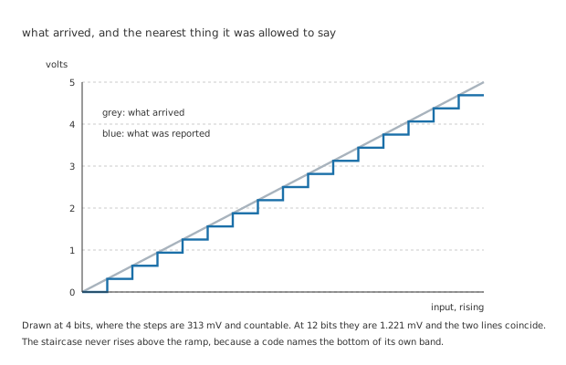
Drawn at four bits, where the steps can be counted. At twelve bits the two lines coincide.
Worked example — How fine the steps are
An invented converter with a 5.000 V full scale divides it into as many steps as its bits allow.
8 bits gives 256 steps of 19.53 mV. 12 bits gives 4096 steps of 1.221 mV. 16 bits gives 65536 steps of 76.29 µV.
Between the coarsest and the finest, a factor of 256 — every bit halves the step.
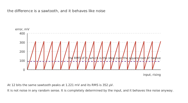
It is not noise in any random sense. It is completely determined by the input, and it behaves like noise anyway.
The staircase lies below the ramp everywhere, because a code names the bottom of its own band. The gap is zero at every boundary and one full step just before the next, so it averages half a step and its RMS is the step divided by the square root of twelve.
Worked example — What that error comes to
At 12 bits the step is 1.221 mV, and the worst error is the whole of it: 1.221 mV, just before the next boundary.
Spread across a rising input the RMS of it is 352 µV.
Nothing about the converter can make that smaller except more bits, because it is what having a finite number of levels means.
Engineer
What a bit is worth, and what a label promises
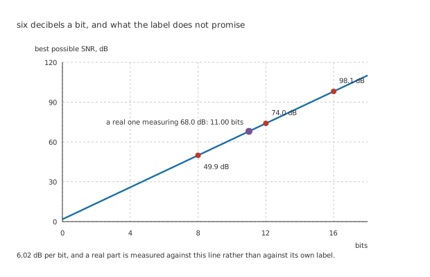
A real part is measured against this line rather than against its own label.
Worked example — Turning steps into decibels
The best a converter can do is the ratio of the largest signal it takes to the RMS of its own quantisation error, and both follow from the number of steps.
8 bits allows 49.9 dB, 12 allows 74.0 dB and 16 allows 98.1 dB.
Every bit is worth 6.02 dB, which is where the familiar six-decibels-a-bit comes from, and it is exact rather than approximate: it is twenty times the logarithm of two.
That line is a ceiling and not a promise. A real converter has thermal noise in it, non-linearity, a reference that moves, and a supply that is not quiet, and all of that lands on the same measurement.
Worked example — What a real part is actually doing
Measure a twelve-bit part and suppose it manages 68.0 dB, against the 74.0 dB its bit count allows.
Read that back through the same relation and it corresponds to 11.00 bits.
1.00 lost, and 6.01 dB of it, from a part whose label says twelve.
That number has a name — the effective number of bits — and it is the one worth comparing between parts, because the label counts pins on a bus rather than levels that can be distinguished. It is also why the reference matters so much: a reference error goes straight into that budget, and no amount of resolution recovers from it.
Professional
The horizontal axis: the moments it does not look
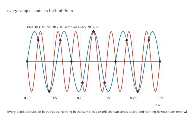
Nothing in the samples can tell the two tones apart, and nothing downstream ever will.
Worked example — Two tones, one set of numbers
Sample at 48 kHz and the interval is 20.8 µs. Half that rate — 24 kHz — is the highest frequency the samples can describe.
A 18 kHz tone gets 2.67 samples per cycle, which is enough.
A 30 kHz tone gets fewer than two, and every sample it produces is identical to one the 18 kHz tone would have produced. It arrives as 18 kHz, on top of the real signal.
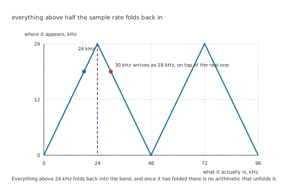
Everything above the half-sample rate folds back into the band, and once it has folded there is no arithmetic that unfolds it.
This is a stronger statement than it first sounds. It is not that the high tone is attenuated, or distorted, or reported with error. It is indistinguishable — the two produce the same numbers, and no processing afterwards, however clever, can separate them. The only fix is to stop the high frequency reaching the converter at all, with a filter in front of it, and that filter is a real part of the design rather than an afterthought.
And a third limit that neither axis explains
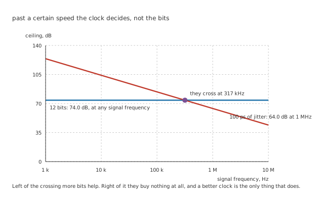
Left of the crossing more bits help. Right of it they buy nothing at all.
A sample is taken at an instant, and the instant is decided by a clock edge that arrives a little early or late every time.
Worked example — What an uncertain instant costs
If the signal is moving when the sample is taken, an error in when becomes an error in what, and the faster the signal the worse it is.
With 100 ps of clock jitter, an 18 kHz signal has a ceiling of 98.9 dB — comfortably above the 74.0 dB that twelve bits allow.
At 1 MHz the same jitter allows only 64.0 dB. The two ceilings cross at 317 kHz.
Below that crossing the bit count is the limit and buying more bits helps. Above it the clock is the limit, and a sixteen-bit part on the same clock returns the same measurement as a twelve-bit one, having cost more.
The other direction
Everything above runs one way. A DAC does it in reverse and inherits the same two limits: a finite number of output levels, and a finite rate at which it can change between them. Its internal ladder is that lesson's subject, along with what happens at the code where every bit changes at once.
What is worth carrying across is that a DAC's output is a staircase too, and it needs a filter after it for the same reason an ADC needs one before it. The steps contain energy at the sampling rate and its multiples, which was never in the signal and is now in the output.
Choosing one
Start from what you need to resolve, not from a bit count. A part's label is a ceiling; its effective number of bits is what you get. A twelve-bit part at 11.00 effective bits and a ten-bit part are the same instrument.
Then check the sampling rate against the whole input, not the wanted part of it. 24 kHz is a hard boundary and everything above it comes back, so the question is what is present rather than what is interesting.
And check the clock before buying resolution. At 18 kHz the jitter is irrelevant here; past 317 kHz it is the only thing that matters.
Common mistakes
- Treating an alias as an error — a 30 kHz tone sampled at 48 kHz produces exactly the samples an 18 kHz tone would. It is not a distorted version of the real signal, it is indistinguishable from a different real signal, and nothing downstream can undo it.
- Reading the bit count as the resolution — 12 bits allows 74.0 dB, and a part measuring 68.0 dB is doing 11.00 effective bits. The label counts bus lines, not distinguishable levels.
- Omitting the filter in front of the converter — the sampling rate does not decide what reaches the input, only what happens to it once it does. Everything above 24 kHz folds back whether or not anybody wanted it.
- Buying more bits to fix a high-frequency measurement — past 317 kHz the 100 ps of clock jitter is the ceiling, and 16 bits on that clock returns the same answer as 12.
- Forgetting the DAC needs a filter too — its output is a staircase, and the steps carry energy at the sampling rate that was never in the signal.
- Quoting quantisation error as a peak when the SNR needs an RMS — at 12 bits the worst error is a full step, 1.221 mV, and the RMS is 352 µV, and only the second one belongs in a signal-to-noise calculation.
Frequently asked questions
Where does the square root of twelve come from?
From the shape of the error rather than from anything about converters. The quantisation error sweeps linearly from zero to one full step and starts again, which is a sawtooth, and the RMS of a sawtooth of peak-to-peak height h is h over the square root of twelve. The same constant turns up wherever a quantity is uniformly spread across a range.
Why does the SNR relation have 1.76 dB in it as well as the six per bit?
Because the two quantities in the ratio are defined slightly differently. The signal is the largest sine that fits, whose RMS is its peak over the square root of two; the noise is the sawtooth's RMS, the step over the square root of twelve. Combining those gives an extra factor of the square root of one and a half, which in decibels is 1.76. It is bookkeeping rather than physics, and it is worth carrying because it is a third of a bit.
Can sampling faster than twice the highest frequency buy anything?
Yes, two things. It moves the aliases further away, which makes the filter in front of the converter far easier to build — the difference between a filter that must cut off within a hair of the band edge and one that has an octave to do it in. And averaging several samples per wanted sample trades that extra rate for resolution, which is oversampling, and is how a converter with very few real bits produces a great many effective ones.
Is the effective number of bits a fixed property of a part?
No, and that is the useful thing about it. It falls with signal frequency, because jitter and internal settling both worsen; it falls with temperature; and it depends on the reference and the supply the part is given. A datasheet quotes it under stated conditions, and a part measured on a noisy board with a mediocre reference will do considerably worse.
What does a converter do with a signal outside its full scale?
It clips, and clips hard: every input above full scale reports the top code and every input below zero reports the bottom one. There is no soft limiting and no warning, and the harmonics that clipping generates land inside the band along with everything else. A converter run near full scale gets the best signal-to-noise ratio it can, and a converter run at full scale gets none of it.