
Quick Answer
An operational amplifier has two inputs and one output, and it multiplies the difference between the inputs by an enormous gain. That gain is so large that any real signal drives the output straight to a supply rail, which is why an op-amp is almost never used on its own. Feedback is what makes it useful.
Intuition
It only watches who is ahead
A referee at the finish line is not measuring anything. They are not timing the race, they do not care how fast anyone ran, and if the whole field slows down by half they will still call the same winner. All they do is decide which of two runners is ahead, and then say so as loudly as the occasion demands.
An operational amplifier does that with voltage.
It has two inputs. It compares them, ignores everything they have in common, and drives its output in whichever direction says which one is higher. Lift both inputs by five volts together and nothing about the output changes, because nothing about the comparison changed. That indifference to the common level is not a side effect; it is the definition.
What makes an op-amp strange is how loudly it says so. The gain built into one is not ten or a hundred. It is hundreds of thousands, which means a difference far too small to see on a meter is enough to slam the output as far as the supply lets it go. On its own the part is not an amplifier at all. It is a device with an opinion and no restraint, and the entire craft of using one is about restraining it.
Practitioner
Three elements, and everything else is detail
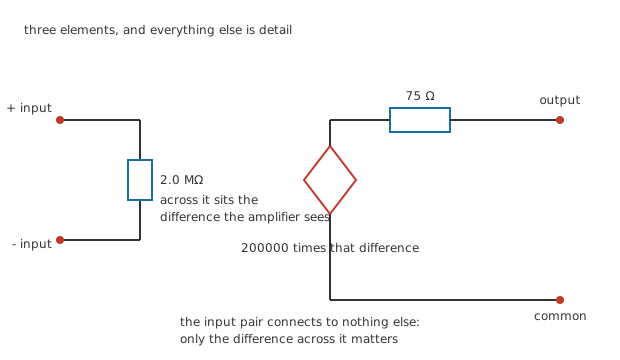
Five nodes and no junction dots anywhere, because the model is a chain rather than a network.
Inside the package there are dozens of transistors: a differential pair at the front, current mirrors setting the bias, a gain stage, an output stage. None of that is what you calculate with. What you calculate with is three elements.
A resistance sits between the two inputs, an invented 2.0 MΩ in this lesson. The voltage across it is the difference, and it is the only input quantity the model contains. A controlled source then produces that difference multiplied by the open-loop gain, an invented 200000. In series with that source sits an output resistance, an invented 75 Ω, and beyond it the output terminal.
Every figure in this lesson is invented in the same way and belongs to no real part. Open-loop gains, input resistances and output currents vary by orders of magnitude across the op-amp family, and the ones that govern a design are on that part's datasheet.
In the other currency the same gain is 106 dB, which is where the decibel figures on a datasheet come from. Either way the number is doing something unusual for an amplifier specification: it is far larger than anybody wants.
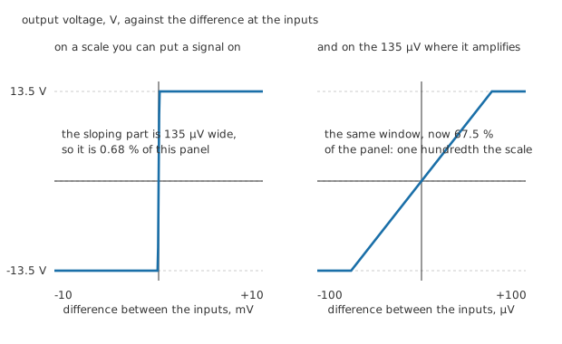
Same amplifier, same vertical axis, horizontal scales a hundred apart.
Worked example — How much difference the output can stand
The output cannot reach the rails. On a 15 V supply it stops 1.5 V short at each end, so it can reach 13.5 V either way, a total span of 27.0 V.
Working backwards through the gain, the input difference that just puts the output there is 67.5 µV.
Beyond that in either direction the output is against a rail and stays there. The whole range over which this part behaves as an amplifier is 135 µV wide.
Put that beside the output span and it is 0.00050 % of it. The left panel above is drawn on a scale you might plug a signal generator into, and at that scale the sloping region is too narrow to see; the right panel is the same characteristic magnified a hundred times, where it finally looks like a line with a gradient.
Both panels are the same part. Nothing switched between them.
Engineer
More gain means less room
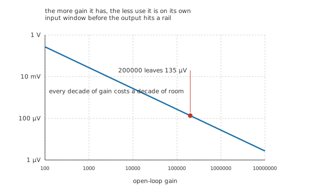
One decade of gain costs one decade of usable input range, and the trade never improves.
The window is twice the output's reach divided by the gain, so it shrinks exactly as fast as the gain grows. A part with a gain of 100 would leave 270 mV to work in, which is a perfectly usable amplifier that you could drive from almost anything. A part with a gain of 10000000 leaves 2.7 µV, which is thermal noise and a warm afternoon.
This is the trap that catches people reading datasheets for the first time. Open-loop gain looks like a figure of merit, and manufacturers compete on it, and a bigger one is genuinely better. But it is not better because you get to use it. It is better because of what happens when you throw almost all of it away, which is what the golden rules are about and is the next lesson.
The one job an op-amp does do well open-loop is deciding which input is higher, since that is all the saturated output is telling you. That job has a name and a lesson of its own: comparators.
It genuinely does not care about the common level
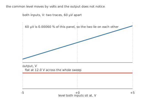
The top panel has two traces on it. At this scale they are one line, and the figure says so rather than pretending otherwise.
Hold the difference between the inputs constant and move both of them up and down together, and the output does not move.
Worked example — A difference small enough to keep the output honest
Set the difference at 60 µV, which is inside the window. The output then sits at 12.0 V, comfortably short of the rail.
Now sweep both inputs together from minus 5.0 V to plus 5.0 V. The output stays at 12.0 V the whole way.
Across that sweep the two input traces are 0.00060 % of the swept range apart, which is why the top panel of the figure shows only one line.
That property is worth more than the gain, and it is the reason op-amps are used to measure things. A sensor bridge sitting on a noisy supply produces a few millivolts of real signal riding on volts of rubbish that both its outputs share, and a differential amplifier can throw the shared part away. How well a real one manages that has a number attached, and instrumentation amplifiers are built around it.
There is a limit on how far the common level may go. The inputs of this invented part accept 12 V either way, which is nearer the rails than the output can reach but not all the way to them. Push past it and the internal stages come out of their working region, and the output does something unhelpful without warning you first.
Professional
What the supply lets it do
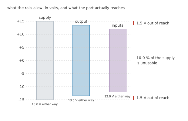
All three bands drawn at the same pixels per volt, so the heights are the voltages.
An op-amp needs power, and every voltage it produces has to come from the supply it is given. Nothing it does can go outside those rails, and in practice nothing gets close to them.
Worked example — What the supply buys, and what it does not
On rails of 15 V either side of common, the output reaches 13.5 V either way.
That leaves 1.5 V stranded at the top and the same at the bottom, which is 10.0 % of the whole supply that no signal can ever use.
The part also draws 1.4 mA with no signal and no load at all, so it burns 42 mW sitting still.
Some op-amps do better than this. A rail-to-rail output stage gets within a few tens of millivolts of each rail instead of a volt and a half, which matters enormously on a single 3 V supply and hardly at all on a bench pair. The phrase is on the front page of a datasheet because it is the first thing a designer on a low supply needs to know.
And what the load lets it do
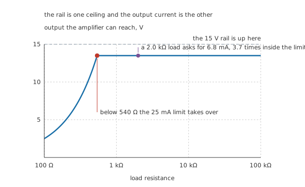
Two ceilings on one output. Which one you meet depends on the load.
There is a second ceiling, and it is a current rather than a voltage. This part will supply 25 mA, and no arrangement of the circuit around it will produce more.
Worked example — The smallest load that still reaches the top
At 25 mA the output can only reach 13.5 V into 540 Ω or more. Below that resistance the current limit governs and the output falls short.
A 2.0 kΩ load asks for 6.8 mA at full swing, which is 3.7 times inside the limit.
Driving it that hard puts 91 mW into the load, against the 42 mW the part burns doing nothing.
The output resistance costs something too, though far less than beginners expect.
Worked example — What the output resistance takes
75 Ω in series with a 2.0 kΩ load is a divider, so the gain seen at the load falls from 200000 to 192771.
In decibels that is 105.7 dB instead of 106 dB, a loss of 0.32 dB.
Which is nothing, and it is nothing for a reason: throwing away a third of a decibel out of a hundred and six matters only if you were relying on the exact figure, and nobody sensible is.
What to take from this
The gain is not a specification you use. It is a resource you spend on accuracy, and the spending is done by feedback.
The two inputs are equals in the model. Nothing in the three-element picture distinguishes them except sign, and neither is a reference.
The output has two ceilings, a voltage set by the rails and a current set by the output stage, and a design meets whichever one it reaches first.
Everything in this lesson is static. Move the signal and the picture changes: the gain falls with frequency, the output cannot move faster than a certain rate, and the inputs are not exactly matched. Those are the subject of real op-amp limitations, and none of them is in the model above.
Common mistakes
- Treating open-loop gain as usable gain — at 200000 the input window is 135 µV wide, which is 0.00050 % of the output's 27.0 V span. Any real signal saturates the part. The gain is spent on accuracy through feedback, not collected at the output.
- Expecting the output to reach the rails — it stops 1.5 V short at each end here, which is 10.0 % of the supply gone. On a bench pair that is a detail; on a 3 V single supply it is most of the signal, and it is why rail-to-rail parts exist.
- Referencing one input to ground in the model — nothing in the three-element picture makes either input a reference. What the amplifier responds to is the voltage across the 2.0 MΩ between them, and both inputs may sit anywhere inside the 12 V common-mode range.
- Forgetting the output current limit — 25 mA into a load below 540 Ω means the output cannot reach 13.5 V no matter what the feedback demands. The circuit will look like a gain error and is a current limit.
- Worrying about output resistance — 75 Ω into 2.0 kΩ costs 0.32 dB of a 106 dB gain. Feedback removes even that, and the parameter is mostly there to explain why heavy loads are a problem at all.
- Reading a datasheet gain figure as a promise — it is quoted at DC, into a stated load, at one temperature, and it varies by a factor of several between parts from the same reel. Circuits are designed so that the exact figure does not matter.
Frequently asked questions
Why make the gain so large if it cannot be used?
Because feedback converts spare gain into accuracy. A circuit built around an op-amp sets its behaviour with a ratio of components and relies on the amplifier to be effectively perfect; the larger the open-loop gain, the closer to perfect it is, and the less the exact figure matters. A gain of 200000 is not there to be used. It is there to be thrown away.
What happens if I connect an op-amp with nothing in the feedback path?
The output sits against one rail or the other, decided by whichever input happens to be higher, including by a fraction of a millivolt of internal imbalance. That is a legitimate circuit when the answer you want is which input is higher, and useless when you wanted an amplifier. Comparators are the parts built for the first job.
Does an op-amp need a split supply?
No. It needs a supply, and the model only cares about the total span between the rails and where the signals sit inside it. A single supply works perfectly well provided the inputs and output stay inside their ranges, which usually means arranging a mid-supply reference for signals to sit on rather than using zero volts.
Why does the output stop short of the supply rails?
Because the transistors in the output stage need some voltage across them to keep working, and how much depends on how the stage is built. 1.5 V at each end is typical of the older designs; a rail-to-rail output stage uses a different topology and gets within tens of millivolts. Neither reaches the rail exactly, because a device with zero volts across it is a short circuit rather than a transistor.
Is the input resistance really megohms?
For a bipolar-input part it is that order, and for an input stage built on field-effect transistors it is far higher and the number stops meaning much. In either case the resistance is rarely the thing that limits a circuit; the small current the inputs actually draw usually matters more, and that is a separate parameter.