
Quick Answer
A comparator answers one question: which of its two inputs is higher. Its output is at one rail or the other and nowhere between. Feed a little of that output back to the non-inverting input and the circuit acquires two thresholds instead of one, which is what stops a noisy signal producing a stream of answers.
Intuition
A thermostat with no deadband
A thermostat that switched the heating off the instant the room reached twenty degrees, and back on the instant it fell below, would be a bad thermostat. Not because the temperature would be wrong, but because the boiler would start and stop every few seconds for as long as the room sat near the setting. The relay would wear out, the boiler would never reach efficiency, and the house would be full of clicking.
Every real thermostat has a deadband. It switches on at nineteen and a half and off at twenty and a half, so once it has made a decision it sticks to it until the room has moved a definite distance in the other direction. The setting has not become vague. It has become two settings, and the gap between them is what makes the answer stable.
A comparator is a thermostat for voltage, and it has exactly the same problem and exactly the same fix.
Its job is to say which of two voltages is higher, and it says so by putting its output hard at one supply rail or the other. That is a decision rather than a measurement, and it is what turns a continuous quantity into something a digital circuit can use. But a real signal near the threshold is not a clean number. It has noise on it, and a comparator with a single threshold answers the noise as faithfully as it answers the signal.
Practitioner
The same feedback, on the other input
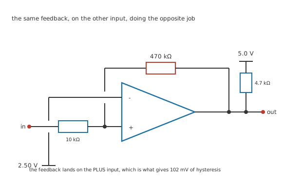
Three junction dots and two deliberate breaks. The feedback lands on the plus input, which is the whole difference.
Every circuit so far has fed its output back to the inverting input. This one does not.
The signal arrives through 10 kΩ at the non-inverting input, the reference sits at 2.50 V on the inverting one, and 470 kΩ runs from the output back to the non-inverting input. Because the feedback reinforces rather than opposes, the circuit has no stable middle: the moment the output starts to move it drags its own input the same way, and it arrives at a rail immediately.
Which is not a failure here. It is the point.
Worked example — Two thresholds instead of one
The non-inverting input sees a mixture of the signal through 10 kΩ and the output through 470 kΩ. It switches when that mixture reaches 2.50 V, and the output is part of the mixture.
With the output high at 4.90 V the input has to reach 2.551 V to tip it. Once it has tipped, the output is at 0.10 V and the input has to fall to 2.449 V to tip it back.
The two are 102 mV apart, centred on 2.50 V, which is the reference.
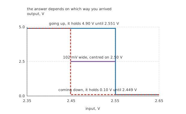
Two paths, because the answer depends on which way the input is moving.
Everything in this lesson is invented and belongs to no real part. The supply is a single 5.0 V rather than the split rails the earlier lessons used, because that is where comparators mostly live: their job is to hand a decision to something digital.
Engineer
What the hysteresis is for
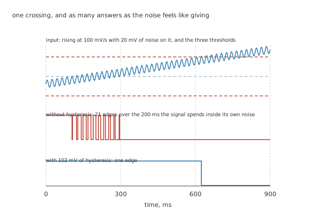
The noise is drawn as a sine so the figure reproduces. Real noise is not a sine.
Here is the failure the deadband exists to prevent.
Worked example — How many answers a single threshold gives
A signal rising at 100 mV/s carries 20 mV of interference at 50 Hz.
It spends 200 ms inside its own noise band, and in that time the noise crosses the threshold repeatedly. The rate estimate says 20 edges; the instance the figure actually draws gives 21, because the phase does not oblige.
With 102 mV of hysteresis, which is 5.11 times the noise, the count is one.
The difference between twenty-one answers and one is not a matter of degree. Whatever is downstream — a counter, an interrupt, a motor contactor — sees each of those edges as a separate event, and no amount of software cleverness afterwards can tell which one was the real crossing.
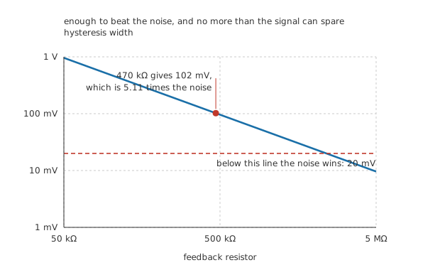
Below the dashed line the noise wins.
Choosing how much
The hysteresis width is the output's span multiplied by the ratio of the two resistors, so it is a straight design choice with a floor and a ceiling.
The floor is the noise. Less hysteresis than the noise is no hysteresis at all, because the noise still crosses both thresholds. 5.11 times is comfortable; twice is defensible; equal is not.
The ceiling is the measurement. The two thresholds are 102 mV apart, so the circuit cannot resolve anything finer than that, and a signal that never travels that far never switches at all. On a level detector watching a slow tank that is fine. On something that has to catch a small excursion it is fatal.
And the centre moves. The thresholds straddle the reference, so raising the hysteresis widens the band about 2.50 V rather than shifting it. That is usually what you want and it is worth checking, because the inverting arrangement behaves differently.
Professional
Why a comparator is not an op-amp
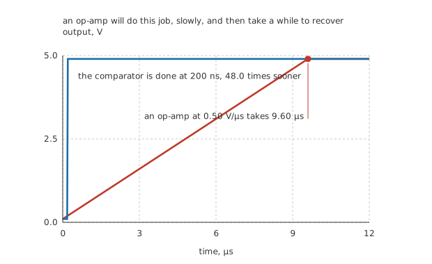
Both traces start low and finish high. Everything between them is the difference.
An op-amp will do this job. It has two inputs, it compares them, and with no feedback its output slams to a rail. People use them this way constantly and mostly get away with it.
Worked example — What it costs to use the wrong part
The output has to cross 4.80 V. A dedicated comparator does it in 200 ns of propagation delay.
An op-amp's output cannot move faster than its slew rate, an invented 0.50 V/µs here, so the same transition takes 9.60 µs.
That is 48.0 times longer, and it is the smaller half of the problem.
The larger half is what the op-amp is doing while it sits at the rail. Its input stage has been driven far outside the range it was designed for and its internal compensation capacitor has charged up, and when the input finally reverses it has to recover from both before it starts moving. That recovery is not on most datasheets, it varies between parts, and it is longer than the slew time.
A comparator has no compensation capacitor, because it is never asked to be stable in a feedback loop. That is what makes it fast, and it is also why a comparator makes a poor op-amp.
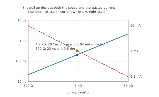
Two quantities, two scales, one on each side. They move in opposite directions.
The output is often not a push-pull stage
Many comparators bring out an open collector or open drain: the output can pull down to 0.10 V and cannot pull up at all. A resistor to the supply does that job, and choosing it is a real decision.
Worked example — What the pull-up costs either way
4.7 kΩ into 20 pF of stray capacitance gives a time constant of 94 ns, so the rising edge takes 207 ns.
That is 1.03 times the comparator's own 200 ns, so the pull-up is now the slower half of the circuit.
Make it smaller and the edge gets faster, at the cost of current: 4.7 kΩ already draws 1.04 mA whenever the output is low.
The compensation is that an open-collector output will pull down to whatever supply the pull-up is tied to, which lets a 5 V comparator drive a 3 V logic input directly, and lets several outputs share one line so that any of them can pull it low. Neither is possible with a push-pull stage.
Reading one on a schematic
Find where the feedback lands. On the inverting input it is an amplifier. On the non-inverting input it is a comparator with hysteresis, and the two resistors tell you how much.
Then find the reference. It is the other input, and everything the circuit does is relative to it.
Check for a pull-up. No pull-up on an open-collector output means an output that never goes high, and it is one of the commonest first faults on a new board.
And check the part. An op-amp in a comparator's place works and is slow, in a way that only shows up when something downstream is counting edges.
Common mistakes
- Using a comparator with no hysteresis on a real signal — a signal rising at 100 mV/s with 20 mV of noise spends 200 ms inside that noise and produces 21 edges where one was wanted.
- Choosing hysteresis smaller than the noise — 470 kΩ of feedback gives 102 mV, which is 5.11 times the 20 mV of noise. A 5.0 MΩ feedback resistor would give 9.6 mV, which the noise crosses freely and which therefore buys nothing.
- Forgetting the hysteresis is also a dead zone — the two thresholds are 102 mV apart, so any excursion smaller than that is invisible. That is the price, and it is paid whether or not the noise was ever there.
- Feeding the output back to the inverting input — that makes an amplifier, not a comparator, and it is the one thing this circuit must not do. The feedback lands on the plus input here.
- Using an op-amp as a comparator without checking the timing — the same 4.80 V transition takes 200 ns from a comparator and 9.60 µs from an op-amp at 0.50 V/µs, which is 48.0 times longer, before recovery from saturation is even counted.
- Leaving an open-collector output without a pull-up — it will pull down and never rise. And with one fitted, 4.7 kΩ into 20 pF takes 207 ns to rise, which is 1.03 times the comparator's own delay: the resistor is now the slow part.
Frequently asked questions
Why does positive feedback give two thresholds rather than making it unstable?
Because the output has only two places to be. In an amplifier positive feedback is a disaster, since the output runs away and there is nowhere useful for it to arrive. Here it arrives at a rail, which is where it was going anyway, and while it sits there it holds the input threshold shifted. The shift is the hysteresis.
How do I decide how much hysteresis to use?
Measure or estimate the noise on the signal, take several times that, and check the result against the smallest change the circuit has to detect. 102 mV against 20 mV of noise is a factor of 5.11, which is comfortable. If several times the noise is larger than the smallest excursion you care about, the answer is a quieter signal rather than less hysteresis.
Can I add hysteresis to an inverting comparator?
Yes, and the arrangement is different: the signal goes to the inverting input, the reference and the feedback both go to the non-inverting one, and the two thresholds straddle a level set by a divider rather than by the reference alone. The output is the other way up. The arithmetic is the same superposition and it is worth doing rather than assuming.
What is propagation delay and how is it different from slew rate?
Propagation delay is how long the comparator takes to react at all, from the input crossing to the output starting to move. Slew rate is how fast a voltage can change once it is moving. A comparator is specified by the first, an amplifier by the second, and the 200 ns and 0.50 V/µs here are not comparable quantities except through the 4.80 V the output has to cover.
Why would anyone want an output that cannot pull high?
Because several of them can share one wire. Any output pulling low takes the line low, and the line only goes high when every one of them has let go, which is a wired-OR without any gates. It also lets the output drive a supply different from its own, since the pull-up decides the high level rather than the comparator does.