
Quick Answer
Inside a 555 are three equal resistors dividing the supply, two comparators watching the taps, and a latch that remembers which of them spoke last. Because the thresholds are fractions of the supply rather than fixed voltages, the timing an external resistor and capacitor produce does not depend on the supply at all.
Intuition
The toaster does not count
Nothing inside a toaster measures time. There is no clock, no counter, nothing that knows what a second is. What there is instead is a strip of metal warmed by the element, bending steadily as it heats, and a latch that lets go when the strip has bent far enough. The knob moves where "far enough" is.
The arrangement has three parts and each does one job. Something changes steadily. Something watches for it to pass a mark. Something remembers the decision, so that the bread stays down until the mark is passed and then stays up afterwards.
A 555 is that arrangement made electrical, and it has exactly those three parts. A capacitor charging through a resistor is the strip. A pair of comparators are the marks. A latch is the thing that remembers.
What makes it worth a lesson rather than a paragraph is a detail of how the marks are set. They are not voltages. They are fractions of whatever supply the chip is given, and that one decision is why a 555 keeps time on a fading battery, why the same circuit works on three volts and on fifteen, and why the part outlived every other timing chip of its generation.
Practitioner
A divider, two comparators, and a memory
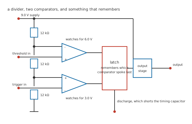
Four junction dots, and two deliberate breaks where the divider column crosses the input runs.
Three equal resistors stand across the supply. Two comparators watch the two taps between them, one from each end. Their outputs set and reset a latch, and the latch drives both the output pin and a transistor that can short the timing capacitor to ground.
The resistors are an invented 12 kΩ here, and their value is a real part's business. What is not invented is where the taps land. Three equal resistors divide anything into thirds, so the upper tap is at two thirds of the supply and the lower one at one third, whatever the resistors are.
Worked example — Where the taps sit
On a 9.0 V supply the divider puts the upper tap at 6.0 V and the lower at 3.0 V.
As fractions those are 66.7 % and 33.3 %, and they will be those fractions on any supply at all.
The divider draws 250 µA of its own doing this, which is the chip's quiescent current before anything else is connected.
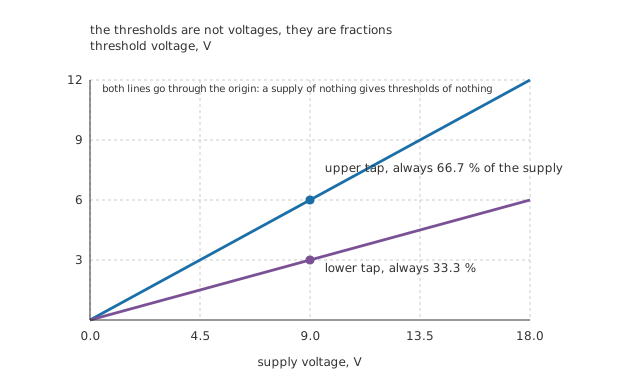
Both lines through the origin, because a divider's output is proportional to its input.
The upper comparator watches the threshold pin against the upper tap and sets the latch when the pin goes above it. The lower comparator watches the trigger pin against the lower tap and resets the latch when the pin goes below it. Between them nothing happens, which is hysteresis arranged out of two comparators rather than one with feedback.
Engineer
Where the supply goes
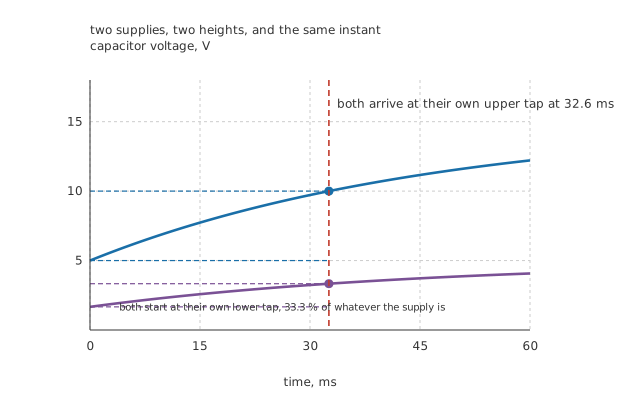
Two supplies, two heights, and one vertical rule through both crossings.
Now hang a resistor and capacitor on the threshold and trigger pins together, and let the capacitor charge from the lower tap towards the supply.
Worked example — How long it takes to cross
With 47 kΩ and 1.0 µF the time constant is 47 ms.
The capacitor starts at 3.0 V, which is a third of the way up, and heads for 9.0 V. It has two thirds of the remaining gap to cover before it reaches 6.0 V.
Two thirds of the gap leaves a third, so the gap halves, and halving takes the time constant multiplied by the natural logarithm of two: 32.6 ms.
Notice what is missing from that answer. The supply voltage entered the arithmetic twice, once in where the capacitor started and once in where it was heading, and it cancelled. The interval depends on the resistor, the capacitor and the number two, and on nothing else.
Worked example — The same components on two supplies
At 5.0 V the taps are at a third and two thirds of that, and the interval works out at 32.6 ms.
At 15 V the taps are three times higher, and the interval is 32.6 ms.
The spread between them is 0.0 %, which is not an approximation but exactly zero: the supply is not in the answer.
That is the whole reason this arrangement won. A timer built with a fixed reference voltage would drift with the supply, drift again with temperature as the reference drifted, and need a regulator in front of it. This one needs neither, and it will keep the same time on a battery all the way down until the chip stops working.
Every figure in this lesson is invented and belongs to no real part.
Professional
The pins that make it flexible, and the one that catches people
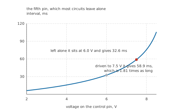
The curve steepens because the upper threshold is approaching the supply it is charging towards.
The upper tap is brought out to a pin. Left alone it sits where the divider puts it; driven from outside, it becomes whatever you make it, and the lower tap follows at half of that because the divider's lower resistor is still there.
Worked example — Moving the mark
Drive the control pin to 7.5 V. The upper threshold is now that, and the lower one is 3.75 V.
The capacitor has further to climb and is approaching the supply more closely, so the interval stretches to 58.9 ms.
That is 1.81 times the interval the divider gives on its own, from a pin most circuits never connect.
A voltage on that pin therefore modulates the timing directly, which is the basis of turning a control voltage into a varying pulse width. That circuit gets a lesson later in this department.
Two other pins matter and are simpler. Reset forces the output low whatever the comparators think, and it must be tied to the supply if it is not being used, because an unconnected reset picks up interference and produces a timer that occasionally stops. Discharge is the collector of the transistor the latch drives, and it is how the timing capacitor gets emptied.
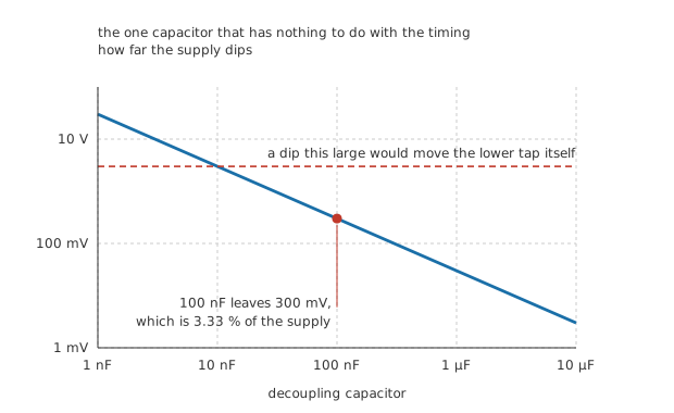
The dashed rule is the lower tap's own voltage. Above it the dip would move the thresholds.
The capacitor that has nothing to do with the timing
Worked example — Why every 555 circuit has a 100 nF beside it
When the output changes state both of its transistors conduct together for a moment. Give that an invented 300 mA lasting 100 ns, which is 30 nC of charge the supply has to find instantly.
With 100 nF across the supply pins the rail dips 300 mV, which is 3.33 % of the supply.
Without it the dip is whatever the supply wiring's inductance allows, which is far more, and it lands on the thresholds themselves because they are fractions of that rail.
This is the failure that makes a 555 circuit produce two pulses where one was wanted. The output switches, the rail dips, the dip moves the trigger threshold, and the chip triggers itself. The fix is a capacitor at the chip's own pins, and it has nothing to do with the timing capacitor at all.
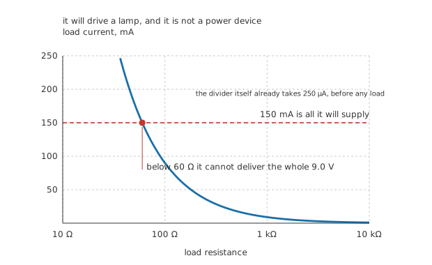
A logarithmic resistance axis, and a flat limit the curve runs into.
What it will and will not drive
Worked example — The output's own limit
The output will supply 150 mA, which at 9.0 V is enough for anything above 60 Ω.
That is a small lamp, a relay coil, a piezo sounder or a logic input, directly and with no transistor.
It is not a motor, not a solenoid of any size, and not a loudspeaker, and the chip's own 250 µA of quiescent current also rules it out of anything that has to sit idle on a battery for months.
And the two circuits everyone builds with it are the next two lessons. Wire the capacitor so it charges through one path and discharges through another and it runs on its own, which is the astable. Wire the trigger to a button instead and it makes one pulse per press, which is the monostable.
Common mistakes
- Thinking the thresholds are voltages — they are fractions. Three equal resistors put the taps at 33.3 % and 66.7 % of whatever the supply is, which is 3.0 V and 6.0 V on 9.0 V and something else on anything else.
- Regulating the supply for timing accuracy — the interval is 32.6 ms at 5.0 V and 32.6 ms at 15 V, a spread of 0.0 %. The supply cancels out of the arithmetic exactly, and a regulator buys nothing the timing needs.
- Leaving reset unconnected — it forces the output low when it goes low, and an unconnected pin picks up whatever is nearby. Tie it to the supply unless it is being driven.
- Omitting the supply decoupling — 300 mA for 100 ns is 30 nC the rail has to supply instantly, and 100 nF holds the dip to 300 mV. Without it the dip moves the thresholds, because they are fractions of that same rail, and the chip retriggers itself.
- Driving too much with the output — 150 mA at 9.0 V runs out at 60 Ω. A lamp or a relay is fine; a motor is not, and neither is anything that would rather see a transistor.
- Forgetting the control pin is connected to something — it is the top of the divider, brought out. Leaving it open is normal, and a capacitor to ground on it is the usual precaution; driving it deliberately changes the timing by a factor of 1.81 at 7.5 V.
Frequently asked questions
Why is the interval the time constant multiplied by the logarithm of two?
Because the capacitor starts a third of the way to the supply and finishes two thirds of the way, so the gap it still has to cover goes from two thirds to one third: it halves. An exponential approach halves in a fixed time, and that time is the time constant multiplied by the natural logarithm of two, which is about 0.693 of it.
Does the supply voltage really not matter at all?
For the timing, no, and that is exact rather than approximate. What the supply does affect is the output's voltage, the chip's own current consumption, and how much a given amount of noise on the rail is worth relative to the thresholds. It also affects the discharge transistor's saturation voltage slightly, which is where a real part's timing does depend on the supply, in the fourth significant figure.
What is the control pin actually for?
It is the top of the internal divider, brought out so you can override where the upper threshold sits. Most circuits leave it open with a capacitor to ground, which keeps noise off the divider. Driving it turns the timer into something whose interval follows a voltage, which is how a control signal becomes a varying pulse width.
Why does the datasheet insist on a decoupling capacitor?
Because the output stage draws a large current spike each time it changes, and the thresholds inside the chip are fractions of the supply rail. A dip on that rail moves the thresholds while the circuit is switching, which is exactly the wrong moment. 100 nF close to the chip's own pins holds the dip to a few hundred millivolts and the problem disappears.
Is a 555 a good choice today?
For a one-off timing job on a board that has no microcontroller, often yes: it needs no code, no crystal and no regulator, and it works from a wide supply range. Where a microcontroller is already present it is almost never worth a separate chip, and where the timing has to be accurate a crystal-derived count beats an RC by orders of magnitude. It survives because it is cheap, forgiving and needs nothing.