
Quick Answer
Wire a 555's threshold and trigger pins together and hang a capacitor on them, charging through two resistors and discharging through one, and it runs on its own. The capacitor swings between the two internal taps forever, and the two resistors set the two halves of the cycle separately.
Intuition
A tap that will not stop
A tap that has not been turned off properly drips, and it drips at a rate. Not a rate anybody chose: water gathers at the lip until the drop is heavy enough to fall, then falls, then the lip starts gathering again from nothing. Turn the tap a little further open and the drips come faster. Turn it back and they slow. The rhythm is exact enough to keep you awake and nobody set it.
Nothing in that arrangement counts. There is no clock, no oscillator, no timekeeping of any kind. There is one thing that fills steadily, one condition that empties it, and the fact that emptying puts it back where filling began.
The 555 astable is that, and this lesson is mostly about the two halves not being the same length.
Filling takes as long as it takes. Emptying is a different process, down a different path, and the circuit's most awkward property comes straight out of that asymmetry: the output is high for longer than it is low, always, and no choice of resistors makes the two equal.
Practitioner
Two resistors up, one resistor down
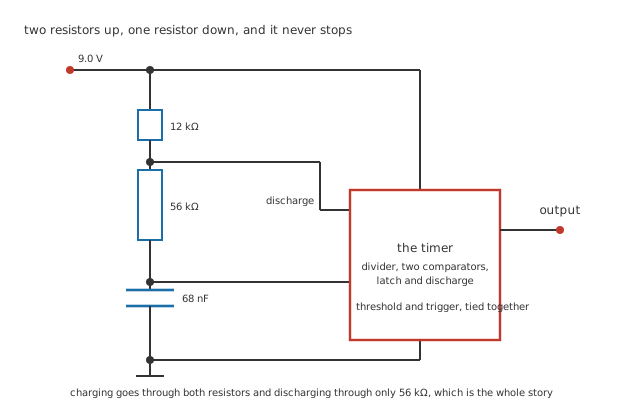
Four junction dots. The threshold and trigger pins are tied together, which is what makes the circuit run.
The previous lesson left the timer with a capacitor being charged and a latch waiting for it to arrive. This one closes the loop.
Tie the threshold and trigger pins together and put them both on the capacitor. Now the same node the upper comparator watches for the top of the swing is the node the lower comparator watches for the bottom of it. Charge the capacitor through 12 kΩ and 56 kΩ in series, and discharge it through 56 kΩ alone into the discharge pin, and the circuit has nowhere to stop.
Worked example — The half of the cycle that charges
The capacitor climbs from 3.0 V to 6.0 V through both resistors, heading for 9.0 V.
That is the same halving of the remaining gap the timer lesson worked out, so it takes the natural logarithm of two multiplied by the two resistors in series and 68 nF.
Which is 3.21 ms, and the output is high for all of it.
Worked example — And the half that discharges
Then the discharge pin pulls the bottom of 56 kΩ to ground, and the capacitor empties through that resistor alone, heading for zero.
It falls from 6.0 V to 3.0 V, which is again a halving, so again the logarithm of two, this time over 56 kΩ only.
2.64 ms, and the output is low for all of it. 12 kΩ takes no part in this half at all.
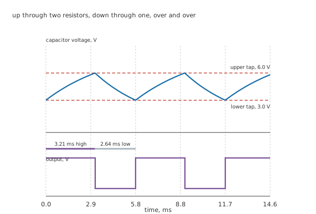
Both halves of the swing are curved. Neither is a ramp, which is what separates this from a triangle wave.
Every figure in this lesson is invented and belongs to no real part. The values deliberately avoid the RC time constant lesson's, so nothing here repeats a scenario you have already met.
Engineer
Half and half is the one thing it cannot do
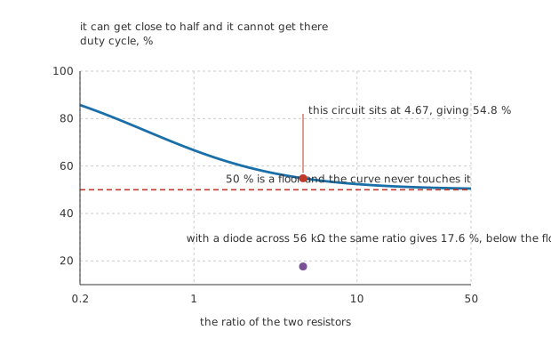
The dashed rule is 50 %, and the curve approaches it without arriving.
Worked example — What comes out
The two halves add to a period of 5.84 ms, so the circuit runs at 171 Hz.
The output is high for 3.21 ms of that, which is a duty cycle of 54.8 %.
Write it in resistances instead and the capacitor cancels: it is the two resistors in series over the same pair with the lower one counted twice, and at this circuit's ratio of 4.67 that is the same 54.8 %.
The high time contains a term the low time does not, so it is always the longer of the two. Make 56 kΩ enormous compared with 12 kΩ and the extra term becomes a small fraction of the total, and the duty cycle approaches 50 % from above. It never arrives, and it can never go below.
That is a genuine restriction. A circuit that wants a symmetrical square wave cannot have one from this arrangement, and the usual answers are to run it at twice the frequency and divide by two, or to put a diode across 56 kΩ so that the charging current bypasses it.
Worked example — What the diode does
With a diode across 56 kΩ, charging goes through 12 kΩ alone and the high time becomes 566 µs.
The low time is unchanged, so the period is 3.21 ms and the frequency 312 Hz.
The duty cycle is now 17.6 %, which is well below the floor the resistors alone can reach.
The diode costs something, and it is worth knowing what: its forward drop sits in series with the charging path, so the capacitor is charging towards a supply about six tenths of a volt lower than it was, and the interval stretches slightly. The clean formula stops being exactly right, and for most purposes that does not matter.
Professional
What sets the rate, and what does not
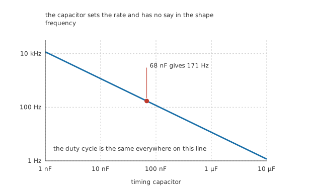
The duty cycle is the same everywhere along this line, because the capacitor divides out of the ratio.
The capacitor is the coarse control. It appears in both halves identically, so changing it moves the frequency and leaves the shape alone, and a decade of capacitance is a decade of frequency.
The resistors do both jobs at once, which is the awkward part of designing one of these: 56 kΩ sets the low time and part of the high time, so moving it changes the frequency and the duty cycle together. 12 kΩ only affects the high time, so moving it changes both as well, in a different proportion. There is no adjustment that changes one without the other, and the practical method is to fix the ratio for the duty cycle you want and then choose the capacitor for the rate.
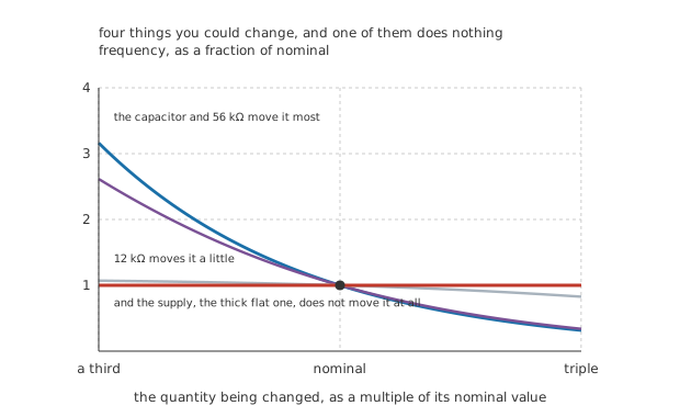
All four pass through the nominal point. One of them is a flat line.
And the supply does nothing at all, for the reason the previous lesson set out: both taps are fractions of it, so it cancels out of the interval before the answer appears. That is the flat trace in the figure, and it is flat exactly rather than approximately.
Worked example — What does move it
Warm the board by 40 °C. Give the resistor and capacitor a combined invented temperature coefficient of 0.020 %/°C.
The time constant rises 0.80 %, so the frequency falls by the same fraction, to 170 Hz.
That is the real stability of an RC oscillator, and it is why anything that has to keep time uses a crystal instead.
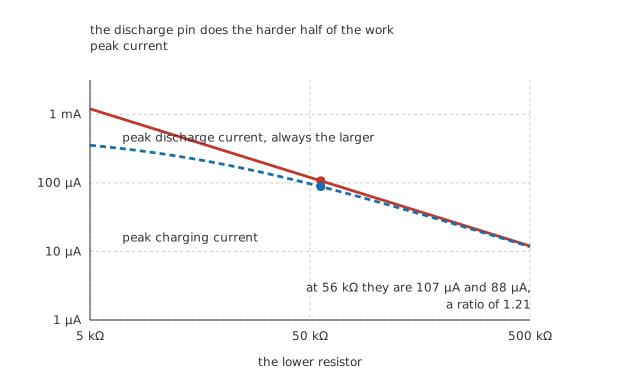
Two traces that converge on the right, because a large lower resistor makes the two paths nearly the same.
What the chip is carrying
Worked example — The currents inside the loop
Charging starts at the lower tap with 3.0 V already on the capacitor, so the initial current is the remaining gap over both resistors: 88 µA.
Discharging starts at the upper tap with the full 6.0 V across 56 kΩ alone, so the initial current is 107 µA.
The discharge pin therefore does the harder half, by a factor of 1.21, and that is what puts a floor under how small 56 kΩ may be made.
Building one
Choose the ratio first, because it fixes the duty cycle and nothing else will.
Then choose the capacitor for the frequency, and expect to need a value that is not in the box.
Keep the resistors in a sensible range. Too small and the discharge pin is carrying milliamps for no reason; too large and the chip's own input current starts to compete with the charging current.
Decouple the supply. The output switches under load twice per cycle, and everything the previous lesson said about the rail dipping onto the thresholds applies here twice as often.
Common mistakes
- Expecting a symmetrical square wave — the high time contains 12 kΩ and the low time does not, so the duty cycle is 54.8 % here and cannot go below 50 % whatever the resistors are. Even a ratio of 50 leaves 50.5 %.
- Trying to set frequency and duty cycle independently with the resistors — 56 kΩ appears in both halves and 12 kΩ in only one, so every resistor change moves both. Fix the ratio for the shape, then pick the capacitor for the rate.
- Forgetting the diode's forward drop — a diode across 56 kΩ gives a duty cycle of 17.6 %, and it also lowers the effective supply the capacitor charges towards by about six tenths of a volt, so the clean 566 µs is a little optimistic.
- Regulating the supply for frequency stability — it does nothing, because both taps are fractions of the supply. What does move the frequency is the components: 0.020 %/°C over 40 °C shifts it 0.80 %, to 170 Hz.
- Making the lower resistor too small — at 5.0 kΩ the discharge pin is carrying 1.2 mA every cycle, against the 107 µA it carries at 56 kΩ. The discharge transistor does the harder half already, by a factor of 1.21.
- Treating the capacitor waveform as a triangle — both halves are exponential segments between 3.0 V and 6.0 V, not ramps. It looks like a triangle only because the swing is small compared with the supply it is heading for.
Frequently asked questions
Why is the high time longer than the low time?
Because charging goes through both resistors in series and discharging goes through only the lower one. The two intervals are the same fraction of their own time constants, and the charging time constant is the larger, so the charging interval is longer. There is no arrangement of two resistors that reverses it.
Why does the logarithm of two appear in both formulas?
Because both halves of the swing cover the same fraction of the remaining gap. Charging from a third to two thirds of the way towards the supply leaves half of the gap it started with; discharging from two thirds to a third of the way towards zero also leaves half. An exponential halves in the time constant multiplied by the logarithm of two, whichever direction it is going.
How accurate is the frequency?
As accurate as the resistor and capacitor, and no better. The chip contributes almost nothing, since the supply cancels and the thresholds are ratios, but a 10 % capacitor gives a 10 % frequency, and the drift here is 0.80 % over 40 degrees. For anything that has to agree with a clock, this is the wrong technique.
Can it run faster than a few hundred kilohertz?
Not usefully. The chip's propagation delay and the discharge transistor's saturation start to be a real fraction of the period, so the formulas stop predicting the answer, and the current spikes get closer together until the supply never recovers between them. A comparator with its own hysteresis is the better circuit above that.
What is the lowest frequency it can reach?
The arithmetic says any, since a larger capacitor or resistor always works. In practice the chip's own input current at the threshold pin competes with the charging current once the resistors are in the megohms, and the leakage of a large electrolytic capacitor competes with it too. A few hertz is comfortable; a cycle time of minutes wants a different approach.