
Quick Answer
A 555 astable compares its capacitor against two taps taken from an internal divider. Drive the control pin and both taps move together, which changes how long the capacitor takes to charge but not how long it takes to discharge. The duty ratio follows the control voltage, and so does the frequency.
Intuition
Move the bar, not the run-up
A high jumper does not change technique between attempts. The run-up is the same length at the same speed, the take-off is in the same place, and what changes between one attempt and the next is the height of the bar. Everything about the approach is fixed and one number moves.
A 555 astable is built the same way. Its capacitor charges through two resistors and discharges through one, and the rate at which it does either is set by parts nobody is going to change while the circuit runs. What can change is where the bar is: the two voltages the capacitor is compared against.
Those two voltages come from a three-resistor divider inside the chip, and one of its pins is the top of that divider. Drive that pin and both taps move. The run-up is unchanged; the bar has moved.
Everything here continues C18's arrangement exactly: 12 kΩ, 56 kΩ and 68 nF on a 9.0 V supply, the same invented timer with a 20 Ω discharge transistor and a 100 nA threshold pin. Undriven, it does what that lesson said it does. Driven, it does this.
Practitioner
One half of the cycle moves and the other does not
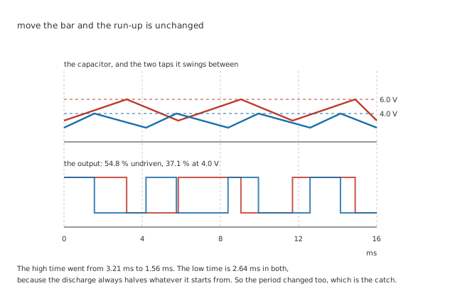
The high time went from 3.21 ms to 1.56 ms. The low time is 2.64 ms in both.
The capacitor charges from the lower tap towards the supply and stops at the upper tap; then it discharges from the upper tap back to the lower one. Driving the control pin to some voltage puts the upper tap there and the lower tap at half of it.
Worked example — Why the low half never moves
Discharging runs from the control voltage down to half of it, through 56 kΩ towards ground.
Whatever the control voltage is, that is always a halving — the same fraction of the same journey — so it always takes the same number of time constants.
2.64 ms, at any control voltage the chip will accept.
Worked example — And why the high half does
Charging runs from half the control voltage up to the control voltage, towards 9.0 V — and the capacitor is aiming at a fixed target while both ends of its journey move.
At the undriven 6.0 V the ratio inside the logarithm is exactly two, the term becomes the familiar natural log of two, and the answer is 3.21 ms.
Drive the pin to 4.0 V and it falls to 1.56 ms. Drive it to 7.0 V and it rises to 4.68 ms.
That reduction is worth noticing rather than skipping. The relation the astable lesson uses is this one with the control pin left alone, and the two agree exactly at that point.
Engineer
What the control pin buys, and what it costs
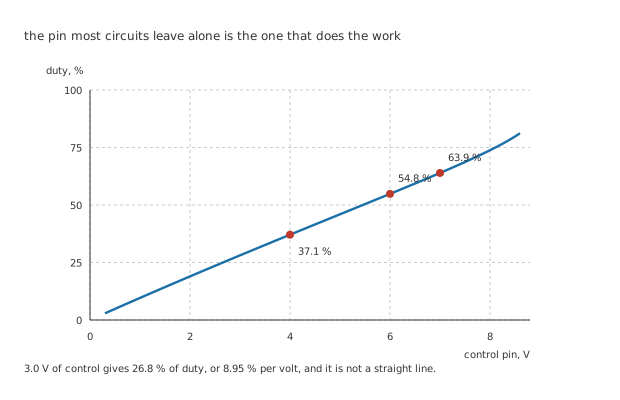
3.0 V of control gives 26.8 % of duty, and it is not a straight line.
Worked example — Turning two times into one ratio
The duty ratio is the high time over the whole period, and only the high time is moving.
At 4.0 V that is 1.56 ms out of 1.56 ms plus 2.64 ms, or 37.1 %. Undriven it is 54.8 %; at 7.0 V it is 63.9 %.
26.8 % of range for 3.0 V of control, which averages 8.95 % per volt and is steeper at the top than at the bottom.
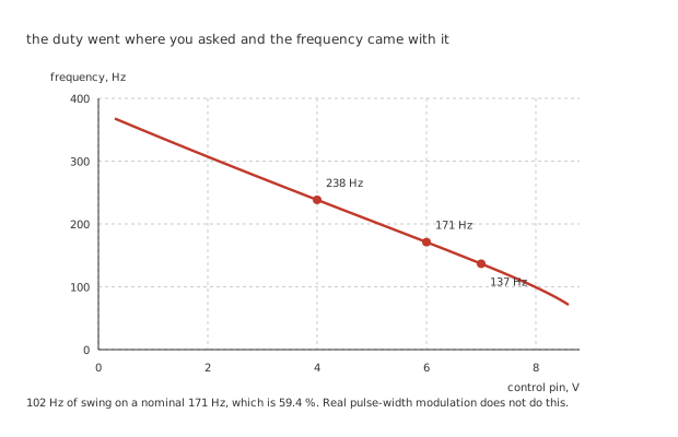
102 Hz of swing on a nominal 171 Hz, which is 59.4 %.
Here is the cost, and it is not a detail. Because only the high half moved, the period moved with it.
Worked example — What the period did while you were not looking
Undriven, the period is 5.84 ms, so the circuit runs at 171 Hz.
At 4.0 V the high time shrank, so the period shrank: 238 Hz. At 7.0 V it grew: 137 Hz.
102 Hz of swing, or 59.4 % of the nominal frequency, for a control range that moved the duty by 26.8 %.
Pulse-width modulation, properly speaking, varies the width and holds the period. This varies both, and whether that matters depends entirely on the load. A heater or a lamp averages over many cycles and does not care. A motor's audible note changes as it is dimmed. Anything downstream expecting a fixed carrier — a filter designed around one frequency, a receiver counting edges — cares a great deal.
Professional
Using it, and knowing where it stops
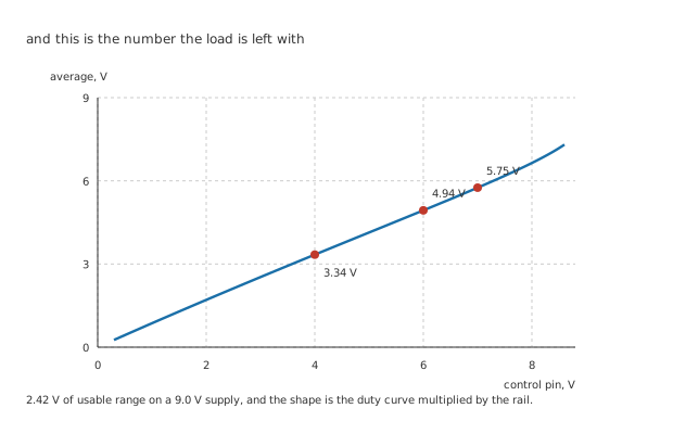
The duty curve multiplied by the rail, which is all that relation is.
Worked example — What a slow load is left with
The load sees the supply for the duty fraction of every cycle and nothing for the rest, so it averages the supply times the duty.
Undriven that is 4.94 V. Across the control range it runs from 3.34 V to 5.75 V, a span of 2.42 V.
Power is a different question, and using the average for it is the classic error. Into 100 Ω, the true RMS is 6.665 V for 444 mW, where the average would have suggested 244 mW — out by 1.82 times. Full on it would be 810 mW.
The duty ratio lesson treats that trap at length and it is worth being careful about here, because a 555 modulator is very often driving something that dissipates.
The pin is not an input
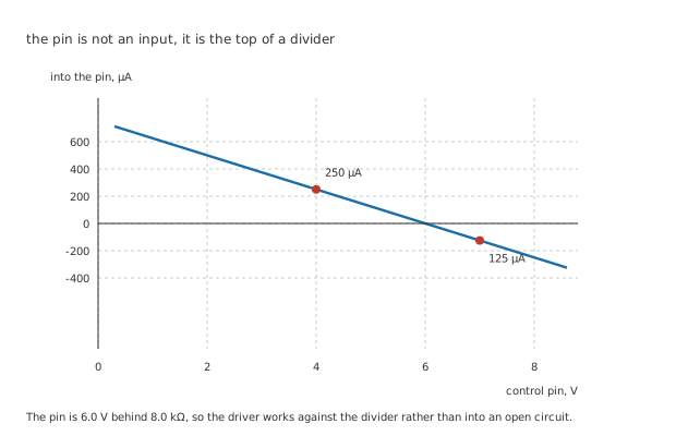
The driver works against the internal divider rather than into an open circuit.
Worked example — What it takes to hold the pin somewhere
The pin is the junction of the divider's top 12 kΩ and the two below it, so from outside it behaves as 6.0 V behind 8.0 kΩ.
Holding it down to 4.0 V means sinking 250 µA. Holding it up to 7.0 V means sourcing 125 µA.
Those are small currents and they are not nothing: 250 µA is 2500 times the threshold pin's own 100 nA, and a high-impedance source will not hold the pin anywhere.
So the modulating signal needs a low-impedance drive — a buffer, an amplifier output, a divider stiff enough to swamp the internal one. A potentiometer straight onto the pin works and shifts the pin's own Thevenin voltage as it goes, which is fine when the result is being adjusted by eye and misleading when it is being calculated.
Where the range gives out
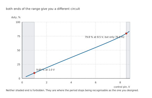
Neither shaded end is forbidden. They are where the period stops being recognisable.
Push the control voltage towards the supply and the logarithm's denominator approaches zero: the high time, and with it the period, grows without limit. At 8.5 V the duty is 79.8 % and the frequency has fallen to 76.6 Hz, less than half the nominal.
Push it towards zero and the high time collapses. At 1.0 V the duty is 9.60 %, and below that the charge time approaches the chip's own propagation delays, which the arithmetic does not model at all.
Neither end is a failure the circuit reports. The output keeps arriving, at a duty the designer asked for and a frequency nobody chose, and the fault surfaces downstream as something else.
Reading one, and choosing whether to build one
Find out whether the control pin is driven or decoupled. A capacitor from it to ground is the ordinary arrangement and means the circuit is not doing this. A resistor, a transistor or an amplifier output means it is.
Then check what the load does with a varying frequency. That is the question this circuit's datasheet cannot answer for you.
And ask whether a fixed carrier is needed. If it is, the answer is a comparator against a ramp, or a controller built for the job — and a switching regulator is that circuit taken seriously. What a 555 gives you is a modulator from one chip and three parts, on a bench, this afternoon.
Common mistakes
- Expecting a fixed frequency — 3.0 V of control moves the duty 26.8 % and the frequency 102 Hz, which is 59.4 % of the nominal 171 Hz. Only the high half of the cycle is being modulated.
- Driving the control pin from a high impedance — the pin is 6.0 V behind 8.0 kΩ, so holding it at 4.0 V means sinking 250 µA. A potentiometer wiper or a sensor output will not do it without a buffer.
- Using the average voltage to work out power — 4.94 V of average into 100 Ω suggests 244 mW, and the true figure from a 6.665 V RMS is 444 mW, out by 1.82 times.
- Pushing the control voltage close to the supply — at 8.5 V the duty reaches 79.8 % and the frequency falls to 76.6 Hz. The circuit is still working; it is no longer the circuit that was designed.
- Assuming the low time can be modulated too — it cannot. The discharge always halves whatever it starts from, so it is 2.64 ms at every control voltage, and that asymmetry is the whole reason the period moves.
- Reaching for this where a real modulator is wanted — a fixed-carrier design needs a ramp and a comparator. This is a bench modulator, and it is an excellent one within what it does.
Frequently asked questions
Why does the high time depend on the control voltage in such an awkward way?
Because the capacitor is charging towards the supply, not towards the tap. The fraction of its remaining journey that the two taps span changes as the taps move, and the logarithm is what turns that fraction into a time. When the taps sit at a third and two thirds of the supply the fraction works out to exactly a half, which is why the undriven case has that tidy natural log of two in it and the driven case does not.
Can I get a duty below a half without driving the control pin?
Yes, with a diode across the larger resistor so that charging and discharging take different paths. That is the arrangement the astable lesson covers, and it moves the duty by changing the resistors rather than the taps. It is fixed once the board is built, which is exactly what makes it a different circuit from this one.
What happens if I drive the control pin with a sine wave?
You get frequency modulation and pulse-width modulation at the same time, which is occasionally what somebody wants — it is how a 555 gets used as a simple siren or a tremolo. The duty follows the sine, the period follows it too, and the result is a warbling tone rather than a clean modulated carrier.
Does the supply voltage affect the duty ratio?
Barely, when the pin is left alone, because the taps are fractions of the supply and both ends of the capacitor's journey scale together. Once the pin is driven from something that does not track the supply, that cancellation is gone: the taps stay where the driver puts them while the charging target moves, so the duty becomes supply-dependent in a way the undriven circuit is not.
How fast can this be modulated?
Not faster than the circuit's own cycle, and in practice a good deal slower. Each output pulse is set by where the taps were when that cycle began, so the modulation is sampled at the carrier rate — 171 Hz here — and asking it to follow anything approaching that gives an output nobody can interpret. A tenth of the carrier is a reasonable working limit.