
Quick Answer
Duty cycle is the fraction of each repeating period a switched waveform spends in its on state, written as a decimal or a percentage. Pulse-width modulation, or PWM, holds the period fixed and varies that fraction, so a load sees an adjustable average without the switch ever leaving full on or full off.
Intuition
On, off, and the level in between
A domestic oven has one heating element and no way to run it at half strength. To hold a set temperature it switches the element fully on, waits, switches it fully off, and repeats. Over a few minutes the food sees something between full heat and none, and where between is decided by how much of each cycle the element spent switched on.
Electronics does the same thing with a transistor, thousands of times a second. The switch is either closed, with the whole supply across the load, or open, with none of it. Nothing sits half way. What gets controlled is the share of each repeating cycle the switch spends closed, and that share is the duty cycle.
Take a 12.0 V supply switched on for 30 % of every cycle. A load too slow to follow the individual pulses behaves as though it were connected to a steady 3.6 V. Lengthen the on-time to three quarters of the cycle and the same rail hands the load an average of 9.0 V.
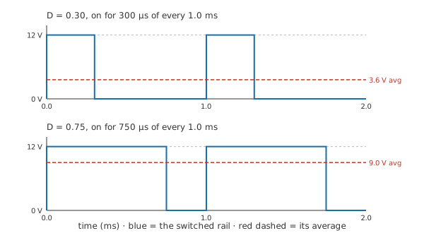
Varying the on-time while the repetition rate stays put is pulse-width modulation, or PWM. It runs heaters, lamps, motors and supply rails, and it wins on efficiency: a switch that is fully closed has almost no voltage across it, a switch that is fully open carries almost no current, and neither state wastes much. A resistor put in series to drop the same voltage would turn the difference into heat.
Practitioner
From on-time to average volts
Duty cycle compares two times, so it comes out as a pure number with no unit attached. It is quoted either as a decimal between zero and one or as a percentage, both conventions turn up on datasheets and in timer registers, and reading one as the other is the commonest slip.
Once the waveform switches cleanly between zero and the supply rail, the average follows without any further work:
The expression assumes the low level really is zero volts. A switch with a saturation drop across it, or a waveform that idles somewhere above ground, needs its two levels weighted separately.
Worked example — A 12 V rail switched at 1 kHz
The signal repeats at 1.0 kHz, so one cycle lasts 1.0 ms, and the switch is closed for 300 µs of it.
On-time over period puts the duty cycle at 0.30, or 30 % in the other convention.
Across a supply of 12.0 V, that gives an average of 3.6 V.
Stretch the on-time to 750 µs without touching the repetition rate and the duty becomes 0.75, the average 9.0 V.
A duty cycle read off an oscilloscope is a pair of time measurements, with no voltage involved anywhere. Most instruments offer it automatically, and what they time is the interval between two threshold crossings part-way up each edge, so a slow or ringing edge biases the figure they report. Cursors placed by hand on the on-time and the period are slower to use and much harder to fool.
Picking the repetition rate is the other half of the setup. It has to be fast enough that the load cannot follow the individual pulses, and there is no benefit in going faster than that. A lamp or an LED needs a rate high enough to look steady, and steady to a fixed stare is a lower bar than steady to a moving eye or a camera. A DC motor does its own smoothing, since the winding inductance stops the current changing quickly, but a switching rate inside the audible band makes the windings sing, so motor drives are usually pushed above it.
The switch itself has to be driven properly. A MOSFET used as a switch wants a gate signal that puts it hard on and hard off; held part-way, the device sits in its linear region dropping voltage and passing current at once, and the efficiency argument for switching evaporates. An inductive load also needs somewhere for its current to go at turn-off, which is the job of a freewheel diode.
Generating the waveform is the easy part. A microcontroller timer does it in hardware once configured, and a 555 does it with a handful of passives.
Engineer
Why the average voltage gets the power wrong
The average is the right answer to one question: what level a slow load settles at. It is the wrong answer the moment the question is power. Dissipation in a resistance goes as the square of the voltage, and the square of an average is not the average of the squares.
RMS value sets out the operation in general. Applied to a rectangular pulse train it collapses to something short, because the waveform only ever takes two values:
The waveform sits at the supply for a fraction D of every cycle and at zero for the rest, so the mean of the square is D times the supply squared, and its root is the supply multiplied by the square root of the duty. Average voltage scales with the duty; RMS voltage scales with the root of the duty. The two agree only at the extremes, fully off and fully on.
RMS is defined so that the DC power expression carries over untouched:
Worked example — The same rail into a small heater
The heater is 8.0 Ω, and connected permanently across the 12.0 V rail it would take 18.0 W.
Switched at a duty of 0.30, its RMS voltage is 6.57 V and it dissipates 5.40 W.
Square the average of 3.6 V instead and the answer comes out at 1.62 W, low by a factor of 3.33.
That error factor is one over the duty cycle, so it is worst where PWM is most useful. At a tenth duty the average-voltage answer is ten times too small; at a hundredth it is a hundred times too small.
The correct figure has a pleasant property, though. Power came out at the duty fraction of the full-on figure, exactly, and it will do so at any duty, because the duty multiplies the supply squared before the division by resistance ever happens. Power therefore tracks the duty in a straight line even though voltage does not, and a control input that behaves linearly is a great deal easier to work with.
Which number a load responds to depends on what the load integrates. A resistive heater integrates energy, so heating follows the RMS value. An LED's light output is close enough to proportional to its current that brightness follows the average, though the peak current still has to sit inside whatever pulsed rating the part carries. A motor is both at once: torque follows the average current while the copper loss in the windings follows the RMS current, so a motor whose current ripples heavily at low duty runs hotter than its average current suggests.
Both expressions rest on an idealised picture of the waveform and of the load, and a real circuit departs from it.
The transitions are treated as taking no time. Real edges take some, and while the switch is in transit it is neither fully on nor fully off, so the two-level model loses accuracy as the edges grow against the on-time.
The levels are treated as exactly the supply and exactly zero. A saturation drop, a sense resistor in the return path or a diode in series moves both, and the correction is not always small at low supply voltages.
Real loads are not linear or unchanging either. A filament lamp, a thermistor and a motor under load all shift their resistance as conditions move, so the value in the power expression is only the one that applies at the operating point the circuit reaches.
Averaging is a property of the load, not of the waveform. The waveform itself contains the switching frequency and a long series of harmonics above it, and anything fast enough to follow them sees a square wave and no average at all. Turning the waveform into a genuine DC level takes a low-pass filter with a corner well below the switching rate.
Professional
What the switching frequency costs
Resolution is the first thing the switching rate buys or spends. A microcontroller generates PWM by counting a fixed clock to a reload value and comparing against a threshold, so the number of distinct duty settings is the number of counts in one period. Counting 256 steps at the 1.0 kHz rate above needs a timer clock of 256 kHz, and each step moves the average by 46.9 mV on a 12.0 V rail. With the timer clock fixed, doubling the switching frequency halves the number of steps, and a drive that looked smooth at eight bits starts to show its increments.
The other side of the trade is switching loss. A transistor dissipates almost nothing while it is fully on and almost nothing while it is fully off, but during a transition it carries current and holds voltage at the same time, and the peak dissipation in that window is far above either steady state. Suppose the two edges take 100 ns between them. At 1.0 kHz those edges occupy 0.020 % of the period and cost nothing worth measuring. Raise the switching rate to 100 kHz, where a period is only 10 µs, and the same edges now occupy 2.0 % of it. The energy lost per transition has not changed; the number of transitions per second has gone up a hundredfold, and so has the loss.
Loss splits into a conduction term set by the on-resistance and the current, and a switching term set by the frequency and the edge speed. Which one dominates decides what to fix. A hot device at low frequency wants a lower on-resistance or a bigger package; a hot device at high frequency wants faster edges, which usually means a stronger gate drive rather than a different transistor. Both terms end up as power dissipation in the same junction, and the heat sink has to remove their sum.
Faster edges cost something in turn. Interference couples through how quickly a voltage or a current changes, not through how far it swings, so the edge rate that fixes the switching loss is the same edge rate that fills the spectrum, and the loop the switched current takes decides how much of it escapes. EMI and EMC covers the mechanisms. Where a product is sold into a regulated market, the applicable standard sets what it may emit and conformity is shown by test against that standard.
Ripple pulls the other way and usually wins the argument. Whatever filtering sits between the switch and the load has to work at the switching frequency, and a higher frequency means a smaller inductor and a smaller capacitor for the same residual ripple. That trade decides where a switching regulator runs, and it also makes the audible band an awkward place to sit: below it the magnetics grow, inside it the inductor and the ceramic capacitors can be heard.
In a bridge stage the high-side and low-side devices must never conduct together, so an H-bridge inserts a dead time between one turning off and the other turning on. The dead time subtracts from the commanded on-time, which distorts the duty at the extremes and puts a floor under the narrowest pulse the stage can produce. Motor driver ICs handle it internally and state the figure in their timing tables.
Measurement misleads easily on a switched node. A multimeter slow enough to average shows the average, a true-RMS meter shows the RMS value, and an instrument whose bandwidth lands somewhere near the switching rate shows a number that belongs to neither. Reading the duty cycle off a scope and working from the supply voltage is more dependable than any single meter reading.
Common mistakes
- Squaring the average voltage to get power — the average answers what a slow load settles at, not how much heat arrives. Use the RMS value, which for a rectangular pulse train is the supply multiplied by the square root of the duty.
- Assuming brightness, torque and heating all follow one number — an LED tracks the average current, a resistive heater tracks the RMS voltage, and a motor does both at once. Establish what the load integrates before choosing a formula.
- Confusing the decimal and percentage conventions — the same setting reads as a decimal below one or as a figure out of a hundred, and a timer register usually wants neither of them. Check what the field is scaled to before writing a number into it.
- Driving the gate softly — a transistor held part-way on sits in its linear region, dropping voltage and passing current together. Switching is efficient only while the device spends almost no time between its two states.
- Trusting one meter reading on a PWM node — a slow instrument reports the average, a true-RMS instrument reports the RMS value, and the two differ by a factor that depends on the duty you were trying to measure.
- Leaving an inductive load without a freewheel path — the current in a motor or a solenoid cannot stop when the switch opens, and it will force its way out through the switch as an overvoltage.
Frequently asked questions
Does raising the duty cycle raise the voltage?
It raises the average that a slow load settles at. The waveform still swings between zero and the full supply on every cycle whatever the duty, so anything fast enough to follow the switching sees the whole rail on every pulse.
What switching frequency should PWM run at?
High enough that the load cannot follow the individual pulses, and no higher. Going faster costs switching loss in the transistor and puts more energy into the spectrum, while buying smaller filter components and a faster response. Loads that whine set their own floor.
Is PWM analog or digital?
The waveform is digital and the quantity it carries is analog: the information sits in the timing, not in the level. That makes it cheap to generate from a counter and immune to the level errors an analog control voltage would pick up on the way.
Why is switching more efficient than a series resistor?
A closed switch has almost no voltage across it and an open switch carries almost no current, so the product that would become dissipation stays small in both states. A series resistor drops the unwanted voltage while carrying the full load current, and that product is heat by definition.
Can PWM produce a real DC output?
Only after filtering. A low-pass filter with its corner well below the switching frequency removes the switching component and leaves the average, at the cost of a response no faster than the filter. Feedback around such a stage is how a switching regulator holds its output.