
Quick Answer
A motor driver IC is a bridge plus what keeps it alive: logic that cannot be made to short the supply, a current limit that chops rather than trips, and a thermal cut-out that retries. What it costs is a drop in the path and a continuous rating set by the package, not the silicon.
Intuition
The lever you cannot pull
Underneath the floor of a mechanical signal box runs a frame of steel bars, and they decide which levers can move. A signalman who has just cleared a signal for the down line will find that the lever for the crossing points has gone solid: not warned against, not alarmed, solid. The bars have taken the combination out of existence.
The point of the interlocking was never that signalmen are careless. It was that on a bad night, at the end of a long shift, being careful is not a mechanism. A frame that physically cannot express the dangerous combination is a mechanism.
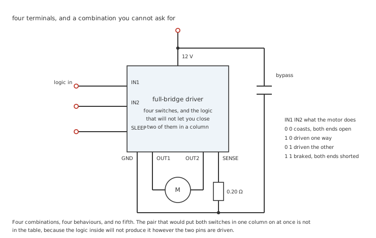
Two pins, four combinations, and the fifth thing a bridge can do is not among them.
A motor driver IC is that frame. Four switches in a bridge will happily destroy themselves if the two in one column are ever on together, and the discrete version of that circuit spends most of its design effort making sure they never are. The integrated version takes the combination out of existence: whatever the two input pins do, and however fast they do it, the part will not close a column.
That is most of what you are buying. The switches themselves are the easy part.
Practitioner
What actually reaches the winding
The switches are not ideal, and what they take is not a rounding error at the voltages small motors run at. There are two ways a driver loses voltage, and they behave completely differently.
Worked example — A resistance in the path
A MOSFET driver has 0.55 Ω on the high side and 0.45 Ω on the low, so 1.00 Ω sits between the supply and the motor.
At 1.0 A that is 1.00 V lost, leaving 11.00 V of the 12 V supply across the winding.
The driver dissipates 1.00 W doing it, and both numbers grow with current.
An older bipolar driver behaves the other way round. Its output devices drop a saturation voltage that barely moves with current — 1.10 V on the high side and 0.90 V on the low here — so it loses 2.00 V whether the motor is drawing an amp or a tenth of one.
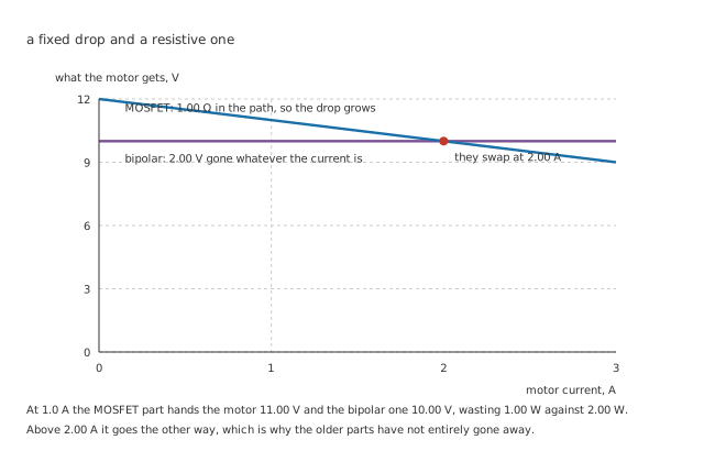
Neither is better. They are better in different places, and the place is decided by current.
Worked example — Where the two swap places
The fixed drop equals the resistive one when 2.00 V equals the current times 1.00 Ω, which is at 2.00 A.
Below that the MOSFET part wins: at 1.0 A it hands the motor 11.00 V against 10.00 V, and wastes 1.00 W against 2.00 W.
Above it the older part wins, because its loss has stopped growing and the other one is still going up as the square.
This is the single most common surprise with small motor projects. A motor characterised on a bench supply behaves differently through a driver, and it is not mysterious: it has less voltage. Everything that lesson says about torque and speed still holds — it just holds at the voltage the winding actually sees.
Engineer
The package, not the silicon
Every datasheet leads with a current. It is almost never the current the part will carry for more than a moment, and the reason is not marketing. A peak rating describes what the metal will survive; a continuous rating describes what the heat allows, and the heat depends on where the die is mounted.
Worked example — The same die, two packages
The conduction loss is the current squared through 1.00 Ω, and it lands on a junction that is allowed to reach 125 °C.
In a package of 45 °C/W from a 25 °C ambient, that permits 1.491 A. In one of 110 °C/W it permits 0.953 A.
Against a headline rating of 2.5 A, the second package holds 38.1 % of it.
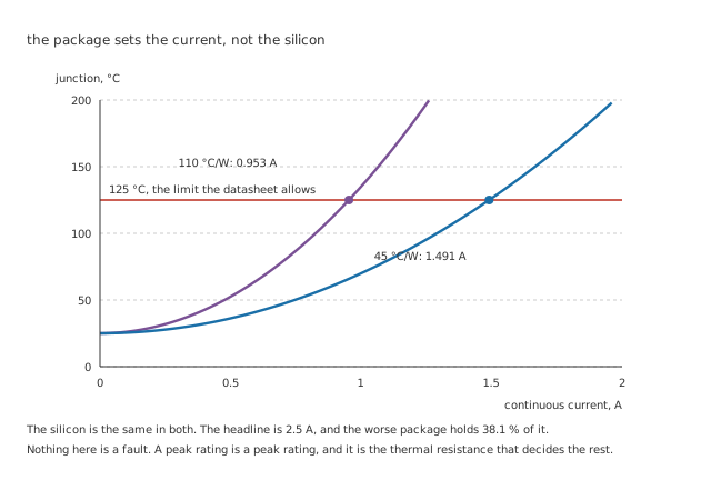
Both curves are the same silicon. The only difference is what the heat can leave through.
Nothing about that is a defect, and the datasheet is not hiding it — the thermal resistance is printed a page or two later, usually with a note about how much copper the measurement assumed. That note matters more than most people expect, because the number quoted is for a board that is largely a heatsink, and a two-layer board with a thin trace to the pad will not achieve it. How much the package decides is a subject of its own, and this is the sharpest case of it.
The practical version is short: at 1.0 A the good package sits at 70.0 °C, which is comfortable, and a motor that draws twice that continuously needs a different package or a different plan.
Professional
What happens when the shaft cannot turn
A motor that cannot turn generates no back-EMF, so it is only its winding resistance, and it takes whatever the supply can push through it. This is not a fault condition — it happens every time a mechanism reaches an end stop, every time something jams, and for a moment at every start.
Worked example — How much a stall asks for
The loop is 1.00 Ω of driver, 0.20 Ω of sense resistor and 3.5 Ω of winding, so 4.70 Ω in total.
On 12 V a stalled motor would take 2.553 A, against the 1.491 A the better package allows continuously.
The current limit exists because 2.553 A is well past what the package can carry, and with a time constant of 532 µs the winding gets most of the way there inside a millisecond.
The limit chops rather than trips
An integrated driver watches the voltage across a sense resistor, and when it reaches a threshold it turns the bridge off — but only for a fixed time, after which it tries again.
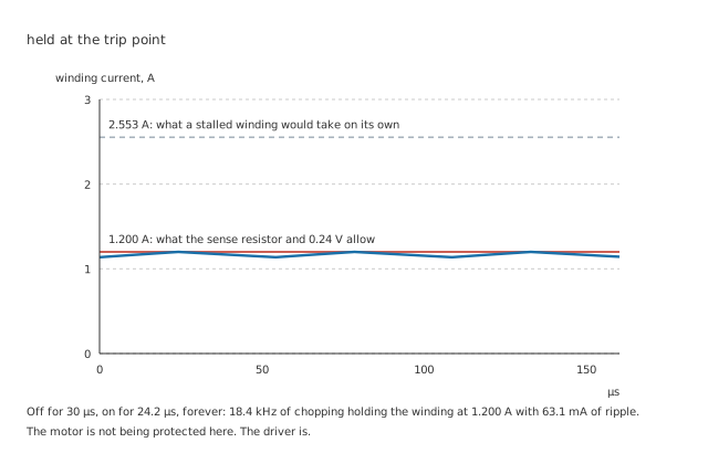
It is not a fuse and it does not latch. It is a regulator made out of a comparator and a timer.
Worked example — What the sawtooth is made of
0.24 V across 0.20 Ω is 1.200 A, which is where the bridge turns off.
The 2.5 mH winding then decays with a time constant of 556 µs, so in the 30 µs it stays off the current falls to 1.137 A — a ripple of 63.1 mA, or 5.26 %.
Getting back up runs on the shorter 532 µs, because the supply is in the loop as well, and takes 24.2 µs. The whole cycle is 54.2 µs, so the part chops at 18.4 kHz with a duty of 44.7 %.
The winding's own inductance is what makes this work. Without it the current would step rather than ramp, and the chopping frequency would be whatever the comparator's propagation delay allowed. With it, the off-time and the inductance set the ripple, which is why the off-time is a datasheet parameter and sometimes a pin.
And when even that is not enough
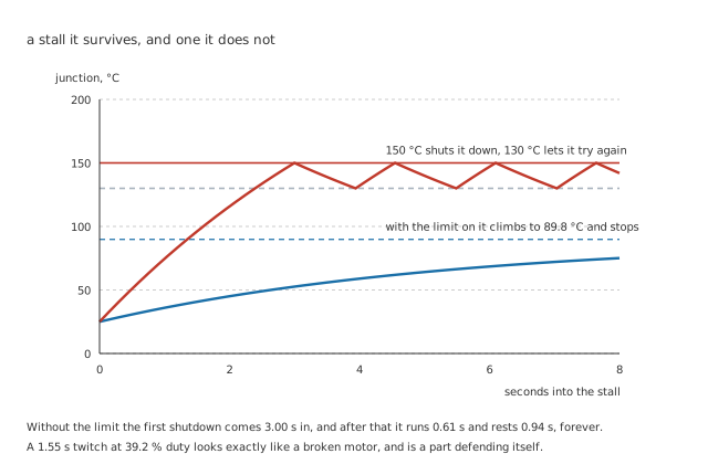
Two behaviours from one part, decided entirely by whether the current limit was set up.
Worked example — The twitch that looks like a fault
Limited to 1.200 A, the driver dissipates 1.440 W and climbs to 89.8 °C, which it can sit at indefinitely.
Unlimited, it dissipates 6.519 W and is heading for 318 °C, so it reaches the 150 °C cut-out 3.00 s in. It cools through 20 °C of hysteresis to 130 °C over 0.94 s, restarts, and gets back to the cut-out in 0.61 s.
That is a 1.55 s cycle at 39.2 % duty, and it will continue for as long as the shaft cannot turn.
Those times come from treating the junction as a single lump with a capacity of 0.12 J/°C behind its thermal path, which gives a time constant of 5.4 s. A real die has a ladder of them rather than one, so the shape is right and the exact seconds are a model — but the behaviour is real and it is worth recognising. A motor that runs for half a second, stops for a second, and does it again is not a bad connection and not a failing controller. It is a part that has been asked to do something it cannot do, and is refusing in the only way it has. The first-order response doing the refusing is the same one that governs every capacitor charging.
Why the timing table has a frequency limit
Every switching edge costs energy, and an integrated driver's edges are slow — deliberately, because fast edges on a motor cable are an emissions problem.
Worked example — Where the budget runs out
The package can lose 2.222 W in total, and 1.00 W of it is already gone to conduction at 1.0 A.
With 1.0 µs edges, switching at 20 kHz costs 240 mW, which is 24.0 % of the conduction loss on its own.
The two meet the budget at 102 kHz, which is the ceiling the timing table quotes.
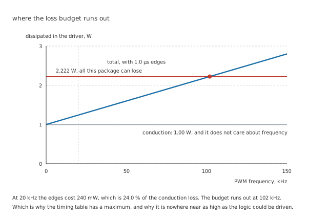
The conduction loss does not care about frequency. Everything above the grey line does.
There is a floor as well as a ceiling, and it is not thermal: below about 20 kHz the switching is inside the range a motor's own structure will radiate as sound, and a whine at the PWM frequency is the usual reason for choosing one. Duty cycle and what it averages to is the other half of that decision, along with the dead time the part inserts, which it will tell you about and will not let you change.
Choosing one
Work out the stalled current first, not the running current. 2.553 A is what the part has to survive, and it is the number the current limit is set against.
Then find the thermal resistance and treat the headline as a peak. 2.5 A on the front page and 0.953 A in the worse package are both true statements about the same part.
Check the drop against your supply. 1.00 V out of 12 V is tolerable; the same current through the same driver on a 5 V supply is a fifth of it, and that is where the bridged-output arithmetic and this one meet.
And use the sense resistor even if nothing seems to need it. It costs one part and converts a thermal-shutdown cycle into a temperature the part can sit at all day.
Common mistakes
- Trusting the headline current — 2.5 A is a peak rating. In a 110 °C/W package the continuous figure is 0.953 A, which is 38.1 % of it, and the difference is entirely thermal.
- Characterising the motor on a bench supply and then fitting a driver — 1.00 Ω in the path takes 1.00 V at 1.0 A, so the winding sees 11.00 V of a 12 V supply and behaves accordingly.
- Assuming a bipolar driver is always the worse choice — its fixed 2.00 V drop beats a 1.00 Ω path above 2.00 A, and small motors are not always small-current.
- Leaving the sense resistor out — without a current limit a stall dissipates 6.519 W instead of 1.440 W, and the part spends its life cycling between 150 °C and 130 °C.
- Reading the retry cycle as a fault elsewhere — a motor that runs 0.61 s and rests 0.94 s is a driver in thermal shutdown, not a loose connection.
- Choosing the PWM frequency from the microcontroller's convenience — the edges cost 240 mW at 20 kHz here and the budget runs out at 102 kHz, and below 20 kHz the motor sings.
- Adding external dead time on top of the internal dead time — the part already inserts it and states the figure. Adding more only shortens the pulse.
Frequently asked questions
Why is there a sleep pin, and does it matter on mains power?
It matters more than the running current suggests. A driver's own logic, charge pump and current-sense comparator draw current whenever the part is awake, and on a battery that is a load which never stops even when the motor has not moved for a day. Pulling the pin low shuts all of it down to a leakage figure, at the cost of a start-up delay while the charge pump comes back. On mains power the argument is weaker but not zero, because a sleeping driver is also a driver whose outputs are definitely open.
What is the charge pump for?
For turning on the high-side switch. An N-channel device in the high side needs its gate above the supply rail to conduct properly, and there is no such voltage in the system, so the part makes one — usually with a small capacitor and a switch, running continuously. It is why some drivers need an external capacitor on a pin called BOOT or CP, why they have a minimum switching frequency as well as a maximum, and why a bridge held on at 100 % duty for a long time can misbehave on parts whose pump refreshes on switching edges.
Can the current limit be used as a torque control?
Yes, and it is one of the standard ways to drive a stepper. Chopping at a set current holds the winding at that current regardless of supply voltage or winding resistance, which is exactly what torque depends on, and changing the reference changes the torque directly. It is less useful on a brushed DC motor, where speed rather than torque is usually what is wanted, and where the limit is doing safety work that becomes control work only at the stall.
Why does the decay happen through the winding rather than back into the supply?
Because most integrated drivers default to the slow path. When the bridge turns off it can either open both ends, sending the winding's current back through diodes into the supply, or short both ends and let the current circulate. The second decays far more slowly, which gives less ripple for a given off-time, and it is what the 556 µs time constant here assumes. Parts that offer both call it fast and slow decay, and the choice changes the ripple, the audible noise and how quickly the current can be reduced.
Does the sense resistor's own resistance matter?
It does, twice. It is in series with the winding, so it takes voltage away from the motor like everything else in the path — 0.20 Ω here, on top of the driver's 1.00 Ω. And it dissipates, which is why the threshold is usually a low voltage: 0.24 V across 0.20 Ω at 1.2 A is 288 mW in a small resistor. Making the resistor smaller reduces both, at the cost of a threshold that is harder to distinguish from noise on the ground return.