
Quick Answer
An audio power IC is a complete output stage in one package. The supply rail sets how much power it can make, two resistors set the gain, and a coupling capacitor sets where the bass stops. Everything that makes it work — the bias, the compensation, the protection — is inside and cannot be adjusted.
Intuition
Four decisions, and the rest is decided
When a ready meal comes out of the freezer, the only decision left is how long to heat it. Somebody else chose the salt, the fat and the order things went into the tray, and no amount of care in the oven will change any of it. That is the deal, and for most evenings it is a good one: the thing works, it works the same way every time, and nobody has to learn to cook.
An audio power IC is the same deal. The output stage is inside it, already biased, already compensated, already arranged so it does not destroy itself when the output is shorted. You get four decisions and no more, and three of them are components you solder on the outside.
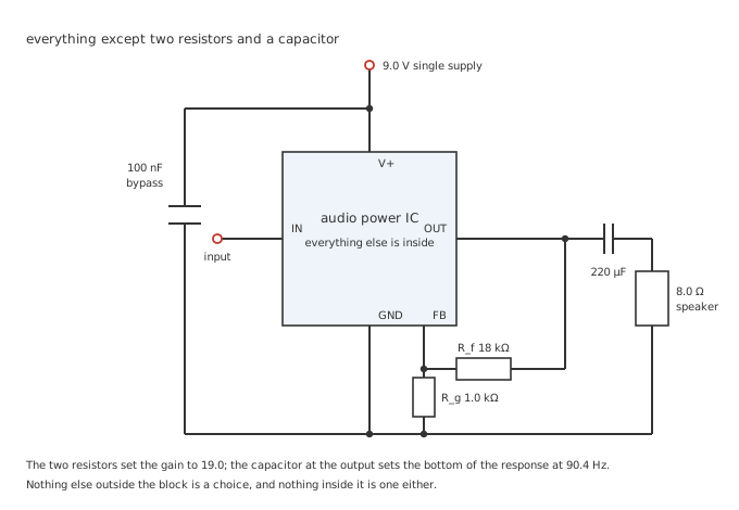
The dotted-in parts are yours. The rectangle is not.
The fourth decision is the supply rail, and it is the one that decides most. A part on a 9 V battery cannot make more power than 9 V will allow into the speaker it is driving, regardless of what its label says, and no choice of resistor moves that number.
Practitioner
The rail sets the power before anything else does
A single-supply amplifier sits its output at half the rail so the signal has room to move both ways, and then it cannot quite reach either end. Some voltage is always left over at the top and the bottom, because the devices doing the driving need a little across themselves to conduct at all.
Worked example — How much of the rail becomes sound
On a 9.0 V supply the output rests at half of it, and loses 0.9 V of headroom at each extreme.
That leaves a peak swing of 3.6 V, which as an RMS value is 2.546 V.
Into 8.0 Ω that is 0.810 W, and no gain setting, no capacitor and no better layout will improve on it.
Under a watt from a nine-volt supply is a smaller number than most people expect, and it is worth sitting with, because it explains almost every design decision that follows. The headroom loss costs more than it looks: 0.9 V at each end of a 9.0 V rail is a fifth of the swing gone, and power goes as the square of the swing.
And the capacitor sets where the bass stops
A single-supply output sits at half the rail, and a speaker connected straight to it would carry that half-rail as a steady current — several hundred milliamps of it, doing nothing but heating the voice coil. A capacitor in series blocks that. It also makes a high-pass filter with the speaker, and the corner is not a detail.
Worked example — What the coupling capacitor costs
Into 8.0 Ω, a 220 µF capacitor puts the corner at 90.4 Hz.
At 40 Hz, which is a note real music contains, that leaves 0.405 of the signal — down -7.86 dB.
Doubling to 470 µF halves the corner to 42.3 Hz, and going to 1000 µF takes it down to 19.9 Hz, which leaves 0.895 of the same note and costs only -0.96 dB.
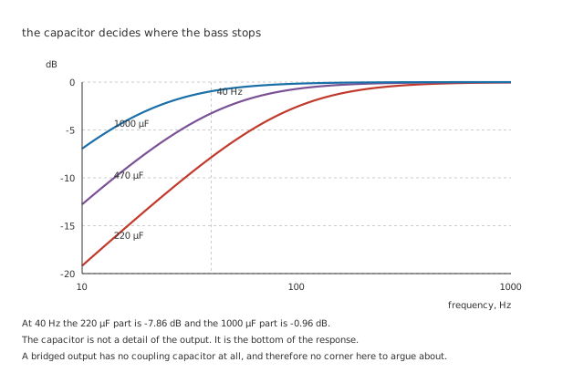
Three capacitors, three different amplifiers as far as the listener is concerned.
The awkward part is the size. A capacitor big enough to keep the corner out of the way is a large electrolytic sitting in the signal path carrying the full output current, and it is often the biggest and most expensive part on the board. That single fact is why most modern parts do not have one at all, which is the bridged output, further down.
Engineer
Everything is fine until the last tenth of a volt
Below the swing it can manage, the part is well behaved and its distortion is roughly constant — the residue of an output stage that is very good but not perfect. Above it, there is nowhere for the peaks to go, and they flatten.
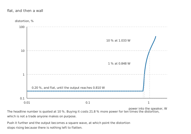
The curve is not drawn steep for effect. It is that steep.
Flattening a sine produces exactly the harmonics that lesson describes, and the fraction of the output that is harmonic rather than signal is what a distortion figure measures. What is striking is how quickly it arrives.
Worked example — Where the headline number comes from
The part runs at 0.20 % distortion all the way up to 0.810 W, where the peaks start to clip.
By 0.848 W it is at one per cent. By 1.033 W it is at ten.
That last figure is the one datasheets print, and buying it costs 21.8 % more power in exchange for ten times the distortion.
A rated power at ten per cent distortion is not a lie, and it is not useless either — it is a fair statement of where the part gives up, and it lets two parts be compared on the same basis. It is just not the power you can use. The number worth writing down is the one at one per cent, or better, the clipping point itself, and on this part those are 0.848 W and 0.810 W against a headline of 1.033 W.
Drive it harder still and the distortion stops climbing, because a fully clipped sine is a square wave and there is nothing left to flatten. That is the ceiling the curve flattens into, and it is a poor place to be listening from.
Professional
Where the rest of the supply goes
An output stage that is halfway between the rails is dropping half the supply across a device that is also carrying the load current, which is heat. It is worst at moderate output and it never reaches zero, because the part draws 5.0 mA even with no signal at all.
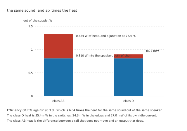
Same speaker, same volume, same evening. Only the electricity bill and the case temperature differ.
Worked example — The heat at full output
Averaged over a cycle, a push-pull output draws 143 mA from the rail, and with the 5.0 mA idle current on top the supply delivers 1.334 W.
0.810 W of that reaches the speaker. The other 0.524 W is heat, which is an efficiency of 60.7 %.
In a package of 100 °C/W that puts the junction at 77.4 °C in a 25 °C room, which is where thermal design stops being optional.
The other way to make the same sound
A class-D part never holds its output halfway. It switches hard between the rails and lets a filter and the speaker's own inductance average the result, which is the same trick a switching regulator uses applied to a signal instead of a rail. A device that is fully on drops almost nothing, and a device that is fully off carries almost nothing, so the only losses are the resistance while it conducts and the moments it spends in between.
Worked example — Adding up the losses that are left
With 0.35 Ω in the path, the 318 mA flowing through it makes 35.4 mW.
The transitions cost 24.3 mW at 300 kHz with 20 ns edges, and the part's own 3.0 mA adds 27.0 mW.
That totals 86.7 mW, against 0.524 W for the same sound — 6.04 times less, an efficiency of 90.3 %, and a junction at 33.7 °C instead of 77.4 °C.
What class D costs instead is a switching edge every few microseconds, sitting a few centimetres from an input that is trying to resolve microvolts. The heat problem is traded for a layout problem, and the layout problem is why the supply bypass on a class-D part is not a formality.
The way out of both problems
Two amplifiers driving opposite ends of the same speaker, one inverting the other, is called a bridged or bridge-tied load, and it does two things at once. The voltage across the speaker is the difference between the two outputs, so it doubles. And neither end of the speaker is at a fixed voltage any more, so nothing has to block a standing offset and the coupling capacitor disappears.
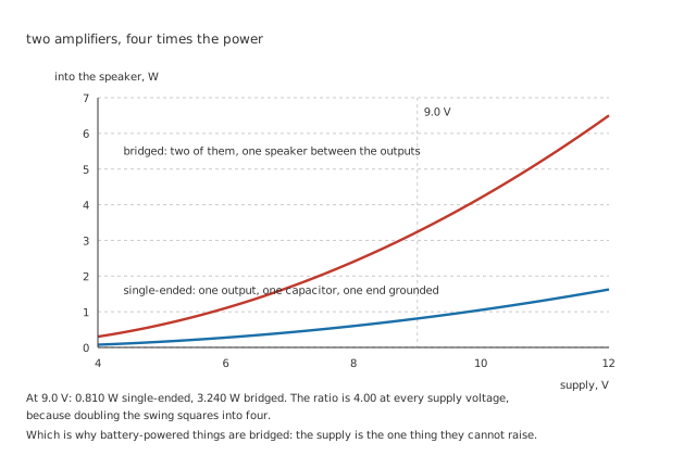
The upper curve is the lower one multiplied by four, at every supply voltage.
Worked example — Why it is four and not two
The swing across the speaker goes from 3.6 V to twice that, and power goes as the square of it.
So 0.810 W becomes 3.240 W: a factor of 4.00, from the same rail, into the same speaker.
It is not free. Two amplifiers draw two amplifiers' worth of idle current, the heat problem gets worse in exactly the proportion the power gets better, and neither speaker terminal can be grounded, which rules out sharing a return with anything else. But on a battery, where the supply is the one thing that cannot be raised, it is usually the whole answer — and it is the reason so many small parts come with two amplifiers in a package that only ever drives one speaker.
The gain is the last decision, and the easiest to get wrong
The two resistors set the gain, and the temptation is to set it high so that anything will drive the part. The cost is not obvious, because the output power does not change: whatever the gain, the ceiling is still 0.810 W. What changes is how much of that ceiling is noise.
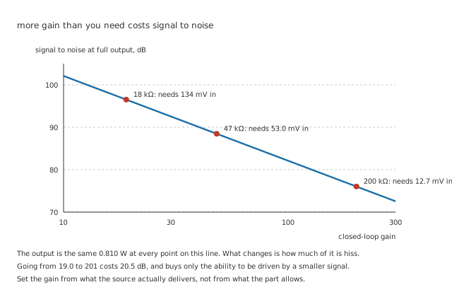
The part's own input noise is amplified along with the signal, and the output cannot rise to compensate.
Worked example — What high gain actually buys
With 1.0 kΩ against 18 kΩ, the gain is 19.0, full output needs 134 mV in, and the 2.0 µV of input noise appears as 38.0 µV out — a ratio of 96.5 dB.
47 kΩ in its place gives 48.0, needing 53.0 mV in for a ratio of 88.5 dB.
Change to 200 kΩ and the gain is 201. Full output now needs only 12.7 mV, but the noise is 402 µV and the ratio has fallen to 76.0 dB.
20.5 dB given away, and the only thing bought with it was sensitivity nothing in the system needed.
Choosing one
Start from the supply and the speaker, not from the part. Those two decide the power, and the power decides which parts are even in the conversation. A rail that cannot be raised and a load that cannot be lowered leaves bridging as the only lever.
Read the rated power's conditions before the number. Ten per cent distortion and one per cent are different questions, and on this part they are 1.033 W and 0.848 W apart.
Work out the heat at the output you actually intend to use. 0.524 W in a small package is a real thermal problem, and it is the reason class D exists in things that run from batteries and live in sealed enclosures.
Set the gain from the source you have. A source that delivers a hundred millivolts does not need a gain of two hundred, and asking for one costs signal-to-noise that nothing downstream can recover.
And check what else the package contains. Many of these parts are the same silicon sold as a motor driver with a different datasheet, because a bridged output driving an inductive load is the same problem in both cases.
Common mistakes
- Reading the rated power as usable power — 1.033 W at 10 % distortion and 0.848 W at 1% describe the same part. Only one of them is a listening condition.
- Choosing the coupling capacitor by size or price — 220 µF into 8 Ω puts the corner at 90.4 Hz and takes 7.86 dB out of a 40 Hz note. That is not a rounding error, it is the bass.
- Setting the gain as high as the part allows — the output ceiling does not move, so all the extra gain does is amplify the input noise. Going from 19.0 to 201 costs 20.5 dB.
- Expecting a 9 V supply to make several watts — 0.810 W is what 8 Ω and that rail allow single-ended. The label on the package does not overrule the arithmetic.
- Grounding one side of a bridged output — there is no ground reference at either speaker terminal, and connecting one to ground shorts an output for half of every cycle.
- Treating class D as free efficiency — the heat falls to 86.7 mW, but a switching edge every 3.3 µs next to a microvolt-level input is a layout problem the linear part never had.
- Ignoring the idle current — 5.0 mA at 9 V is 45 mW dissipated with no signal at all, which on a battery matters more than the efficiency at full output.
Frequently asked questions
Why can't the output reach the supply rails?
Because the devices doing the driving need some voltage across themselves to carry current. In a bipolar output that is a saturation voltage plus whatever is dropped across any emitter resistance; in a CMOS output it is the on-resistance times the load current, which means the loss grows with output rather than staying fixed. Either way a datasheet quotes it at a stated load and current, and it is the difference between the power you calculate and the power you get.
Does a bigger speaker impedance help or hurt?
It hurts for power and helps for everything else. Power into a load is the swing squared divided by the load, so doubling from 8 Ω to 16 Ω halves the available power on the same rail. But it also halves the current, which halves the conduction loss and eases the demand on the supply, and it doubles the coupling capacitor's corner frequency for the same capacitance, which means a smaller capacitor does the same job. Small battery equipment usually goes the other way, to 4 Ω, and pays for the extra power in heat.
What is the bypass pin some of these parts have?
It is a connection to an internal midpoint reference, brought out so a capacitor can hold it steady. Without it the reference moves with the supply and every wobble on the rail appears at the output, which is heard as hum on mains-derived supplies and as motorboating on batteries with high internal resistance. It is not the same thing as the supply decoupling capacitor and it does not replace it.
Why do class-D outputs need a filter if the speaker is inductive anyway?
For the speaker, often they do not — a voice coil is quite happy to average a switching waveform it cannot follow. The filter is there for the wiring. Several metres of speaker cable carrying a square wave at a few hundred kilohertz is an effective antenna, and the resulting emissions are what fails an EMC test rather than anything the listener hears. Short leads inside a sealed plastic case is exactly the situation where the filter is sometimes left out.
Can two of these be paralleled for more current?
Not without care, and usually not at all. Two outputs commanded to the same voltage will differ slightly, and the difference appears across whatever connects them, which is a short circuit as far as both are concerned. Parts designed to be paralleled say so and provide a way to share; parts that are not will fight, and the loser overheats. Bridging two outputs works because they are deliberately driven in antiphase into a load, which is the opposite arrangement.