
Quick Answer
A linear regulator turns the voltage it drops into heat at the full load current. Whether that is fine or fatal depends on how many degrees the path from the die to the room will cost, and on how many degrees are available between the room and the junction limit. Both are arithmetic.
Intuition
Charged by the volt and by the amp
A toll road charges by the mile. Some of them also charge by the axle, so the bill is a product of two things you decided separately: how far you went, and how much of a vehicle you took. Going the long way in a car is cheap. Going the long way in a lorry is not, and neither decision on its own tells you what you will pay.
A linear regulator charges the same way. The bill is the voltage it has to drop multiplied by the current the load draws, and it is paid in heat. Choose a supply five volts higher than you needed and you have taken the long way; ask for half an amp instead of fifty milliamps and you have brought the lorry.
The part itself has almost no say in it. Its efficiency, its dropout, its quiescent current all matter a little. What dominates is the two numbers you chose before you picked the part at all.
This lesson takes the same invented regulator entry one built — 5.0 V out, 5.0 mA of quiescent current — and asks it for 500 mA from 12 V, because 645 mW is not a thermal problem and what follows is.
Practitioner
What the bill comes to, and where the degrees go
Worked example — The toll on this regulator
The pass element drops 7.0 V at 500 mA, which is 3.50 W.
The quiescent current falls through the whole input, adding 60.0 mW. Together, 3.56 W.
The load is receiving 2.50 W for that, an efficiency of 41.3 %. More heat leaves the regulator than power reaches the load.
Now that heat has to get somewhere, and the path it takes has stages. Each stage costs degrees in proportion to the watts crossing it, and the proportion is that stage's thermal resistance.
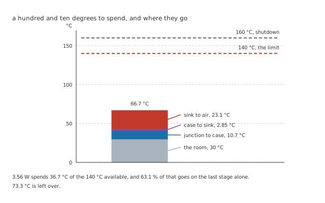
Everything above the grey base is 3.56 W finding its way out.
Worked example — Spending the budget
The path is 3.0 °C/W from junction to case, 0.80 °C/W from case to sink and 6.5 °C/W from sink to air: 10.3 °C/W in all.
At 3.56 W that costs 10.7 °C, 2.85 °C and 23.1 °C — 36.7 °C of rise, of which the sink is 63.1 %.
Starting from a 30 °C room the junction reaches 66.7 °C, leaving 73.3 °C below the 140 °C limit.
Two things in that sum are worth noticing. The junction-to-case resistance is the part's own and cannot be improved without changing the part. The sink-to-air resistance is the largest term and is entirely yours: it is the one a heatsink exists to reduce, and that lesson treats it as a component in its own right.
Engineer
The two ceilings, and the room that eats them
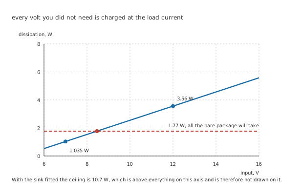
With the sink fitted the ceiling is 10.7 W, which is above everything on this axis and is not drawn on it.
Rearranged, the same relation says what the package will carry rather than how hot it gets.
Worked example — What each arrangement will take
There are 140 °C minus 30 °C to spend, which is a hundred and ten degrees.
With no heatsink the path is 62 °C/W, so the ceiling is 1.77 W. With the sink it is 10.3 °C/W, so the ceiling is 10.7 W.
That is 6.02 times more dissipation from the same die, and this regulator needs 3.56 W, which only the second arrangement allows.
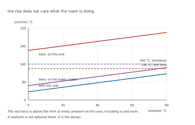
The red trace is above the limit at every ambient on this axis, including a cold room.
The three traces are parallel because the rise does not depend on the room. A hot room does not make the regulator work harder; it starts the sum from a higher number, and every degree of ambient is a degree the design no longer has.
Worked example — What happens with no heatsink at all
Bare, at 3.56 W, the junction would reach 250.7 °C. That is not a design that runs hot, it is a design that shuts down — thermal protection intervenes at 160 °C, and if it did not the part would be destroyed.
Bare on a 7.0 V supply, at 1.035 W, the junction reaches 94.2 °C: inside the limit with no heatsink at all, and staying inside it up to 75.8 °C of ambient.
The part did not change. Neither did the load.
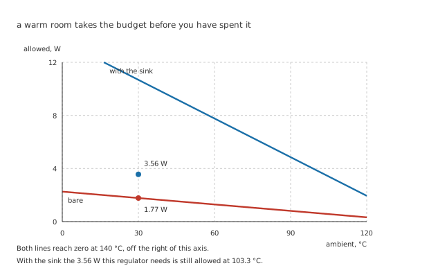
Both lines reach zero at 140 °C, off the right of this axis.
At the 30 °C room the bare package allows 1.77 W and this regulator wants 3.56 W, which is the gap the sink closes. With the sink fitted, that dissipation stays allowed all the way up to 103.3 °C of ambient — which is the number to check against the inside of an enclosure rather than against the room it stands in.
Professional
Sizing the sink, and then not needing it
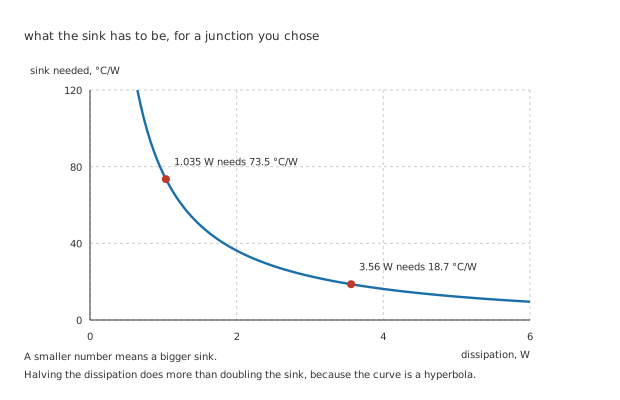
A smaller number means a bigger sink, and the curve is a hyperbola.
Designing to the limit is designing with no margin, so the useful calculation runs from a target rather than from a maximum.
Worked example — Working backwards from a junction you chose
Pick 110 °C as the junction temperature you are willing to live with, in a 30 °C room.
At 3.56 W the whole path may be no worse than eighty degrees divided by the watts, and the package's own 3.0 °C/W and 0.80 °C/W come off the top: 18.7 °C/W is left for the sink.
At 1.035 W the same target leaves 73.5 °C/W, which is a tab and some copper rather than a heatsink.
The hyperbola is why halving the dissipation helps more than doubling the sink. Every heatsink catalogue is a list of numbers between about 1 and 50 °C/W, and the smaller ones are large, heavy, expensive and often need moving air. The curve steepens exactly where those requirements do.
The cheapest heatsink is a supply you chose properly
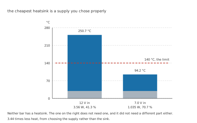
Neither bar has a heatsink. The one on the right does not need one.
Worked example — Changing one number
On 12 V the drop is 7.0 V and the dissipation 3.56 W, at 41.3 %.
On 7.0 V the drop is 2.0 V — still comfortably above the part's dropout — and the dissipation falls to 1.035 W, at 70.7 %.
3.44 times less heat, from the same regulator feeding the same load. Bare, that is 94.2 °C instead of 250.7 °C.
This is the move to reach for first, and it is often available: a transformer tap, a different wall adapter, a pre-regulator, or simply noticing that a 12 V rail was chosen for the motor and the logic never needed it. Where the input genuinely cannot come down — a wide input range, a battery that starts high and ends low — a switching regulator removes the arithmetic rather than reducing it, at the cost of noise and a layout that has to be thought about.
Reading a thermal design that already exists
Find the dissipation first, and find it at worst case. Highest input, highest load, lowest efficiency. A design checked at nominal is a design that has not been checked.
Check which resistance the datasheet quoted. Junction-to-ambient assumes a board; junction-to-case assumes you supply the rest of the path. Using one where the other belongs is the commonest error in this whole calculation, and it is usually a factor of five.
Add the interface. 0.80 °C/W looks negligible next to 6.5 °C/W and it is not zero, and it is much worse dry than with compound. A joint assembled without it can add several degrees per watt.
Then check the ambient you actually have. Inside a sealed enclosure beside a transformer, the air the heatsink is working into is not the air in the room, and the difference has already spent part of the budget before the regulator does anything.
And treat thermal shutdown as a fault, not a feature. 160 °C exists so that a fault does not destroy the part. A design that reaches it in normal service is a design that works until the day the room is warm.
Common mistakes
- Sizing from the load power — the load takes 2.50 W and the regulator dissipates 3.56 W, and it is the second number the package has to survive.
- Checking the thermal sum at nominal input — dissipation is the drop times the current, so the worst case is the highest input at the highest load, and it can be twice the nominal figure.
- Using junction-to-ambient where junction-to-case belongs — 62 °C/W against 3.0 °C/W is a factor of twenty, and mixing them up turns a working design into a shutdown or a heatsink into an ornament.
- Forgetting the case-to-sink interface — 0.80 °C/W with compound is small and not zero, and dry it is several times worse. It is the one term in the sum that depends on how the board was assembled.
- Designing to the junction limit — 140 °C is where the part is no longer specified, not a target. Working back from 110 °C instead is what makes 18.7 °C/W a requirement rather than a hope.
- Reaching for a heatsink before reaching for a smaller supply — 12 V to 7.0 V takes the dissipation from 3.56 W to 1.035 W, which is 3.44 times less heat and removes the heatsink from the design entirely.
Frequently asked questions
Does the load current or the voltage drop matter more?
Neither, because the dissipation is their product and both count linearly. What differs is how much freedom you have. The load current is usually fixed by what the circuit does; the drop is usually chosen by whoever picked the supply, often for a different reason. That is why the drop is the number worth attacking, not because it matters more.
Why is the sink-to-air term so much larger than the others?
Because the last stage is moving heat into air, and air is a poor conductor that has to be persuaded to move. The first two stages are solid paths a few millimetres long: silicon to copper, copper to aluminium through a thin film. The 23.1 °C of the 36.7 °C total that the sink spends is the physics of convection rather than a shortcoming of the heatsink.
Can I use the copper on the board as the heatsink?
Often, and it is how most surface-mount regulators are cooled. A tab or pad soldered to a copper pour behaves as a sink whose resistance depends on the area, the thickness and whether the pour is on one side or two. It is worth calculating rather than assuming, because a small pour can be worse than the free-air figure it replaced by trapping heat under the part.
What actually happens at thermal shutdown?
The regulator turns its output off, cools, turns it back on, and heats up again — so the output pulses on and off at a rate set by the thermal mass around it. The part survives, which is the point, but downstream circuits see the supply appearing and disappearing every few seconds, and the fault is often reported as something else entirely.
Does a heatsink help a part that is already at 250 °C on paper?
That number is a calculation rather than a measurement, because the part shuts down long before reaching it. What the calculation tells you is how far away the design is: 250.7 °C against a 140 °C limit means the path has to improve by a factor of about two, which is a real heatsink rather than a bigger pad. It is exactly the situation where changing the input is worth checking first.