
Quick Answer
A linear regulator sits in series with the load and behaves as a resistor whose value a feedback loop keeps adjusting, so that whatever the input does the output stays put. The difference between input and output is not stored or returned. It is dissipated, at the full load current, as heat.
Intuition
Waste the difference, keep the volts
Put a pressure regulator on a gas cylinder and something slightly odd happens. The cylinder starts at a high pressure and falls all week as the gas goes. The torch on the end never notices. Somewhere in the brass fitting is a diaphragm that opens a little wider as the supply weakens, and what comes out the other side holds the same pressure from the first day to the last.
The regulator is not making pressure. It cannot: nothing comes out that did not go in. What it does is throttle, continuously and by exactly the right amount, and the pressure it takes away is simply gone.
A linear voltage regulator is that fitting. It sits between a supply that wanders and a circuit that would rather it did not, and it holds the output where it was told to by adjusting how hard it restricts the flow. The volts it takes away are not stored, not returned and not recovered. They come out as heat, and how much heat is not the regulator's decision — it follows from the supply you chose to feed it.
That is the whole trade. A shunt regulator makes the same bargain by a different route and wastes current instead of throttling it. This one throttles, which is why it is the part on nearly every board that needs a steady rail.
Practitioner
Three parts and a loop between them
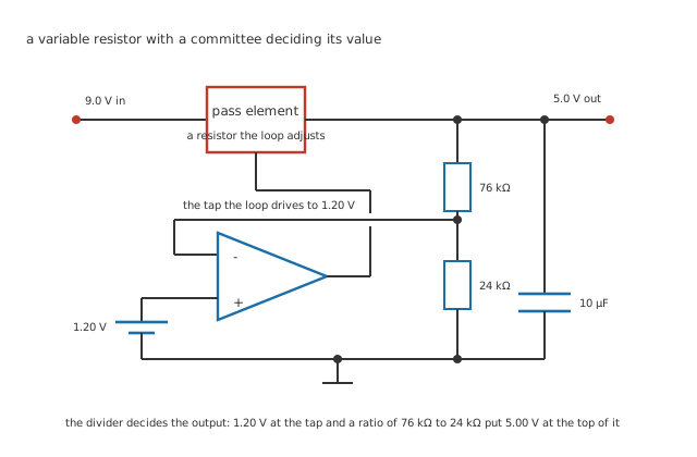
Five junction dots and one deliberate break where the control run crosses the feedback run.
Everything inside is three pieces and the loop that ties them together.
A pass element sits in series with the load. It is a transistor, and the loop uses it as a resistor whose value it can change thousands of times a second.
A reference provides a voltage that does not move — an invented 1.20 V here, and a real one is a lesson of its own.
A divider samples the output. 76 kΩ and 24 kΩ here, drawing 50.0 µA out of the very rail they are measuring.
Worked example — The divider decides, not the transistor
The loop's only ambition is to make the divider's tap equal the reference. It has one knob, the pass element, and it turns it until that happens.
So the output is whatever puts 1.20 V on the tap. With 76 kΩ above and 24 kΩ below, the tap sees the output multiplied by 24 over 100, and the output must therefore be 5.00 V.
Change nothing but the divider and the output changes. Change the pass element for a different transistor and it does not.
That is worth dwelling on, because it is the op-amp golden rules again in different clothing. The high-gain amplifier does not decide the answer. It supplies whatever effort the answer needs, and the passive network around it decides what the answer is.
A fixed regulator has that divider built in and brought nowhere. An adjustable one brings the tap out to a pin so you can pick the two resistors yourself, and the arithmetic above is then yours to do.
Engineer
The two numbers that decide everything
It needs more in than out, and the margin has a name
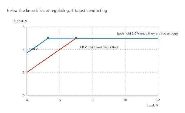
Above their knees the two traces lie on top of one another. Everything that separates them is on the left.
A pass element cannot drop zero volts. It is a transistor being asked to conduct, and there is some minimum across it below which it stops being able to control anything and simply conducts as hard as it can. That minimum is the dropout voltage, and below it the output is not regulated: it is the input, less whatever the element cannot give back.
The invented fixed part here drops out at 2.0 V, so it needs 7.0 V at its input to hold 5.0 V. The invented low-dropout part manages 0.30 V, and needs only 5.30 V. Both numbers are inventions of this lesson and belong to no catalogue part.
Efficiency is a property of the supply, not the part
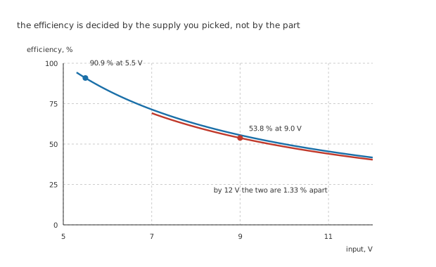
Both traces begin at their own minimum input. Neither can start further left than its own dropout allows.
Worked example — Where the watts go at 150 mA
The load takes 150 mA at 5.0 V, which is 750 mW of useful power.
Fed from 9.0 V, the input supplies that current plus the regulator's own 5.0 mA, so it delivers 1.395 W. The low-dropout part on 5.5 V delivers 825 mW for the same load.
The difference, 645 mW, is heat. Not a small amount of heat next to a useful 750 mW.
Worked example — And why the familiar ratio is optimistic
Everyone quotes efficiency as output over input, which here gives 55.6 %.
Counting the quiescent current, which the input pays for and the load never sees, gives 53.8 % instead. The gap is 1.79 %.
Feed the low-dropout part from 5.5 V and the same load gets 90.9 %, which is 1.69 times better, and its heat falls to 75.3 mW — 8.56 times less than the fixed part throws away.
Notice what actually bought that. The low-dropout part is not more efficient because of anything clever inside it. It is more efficient because its smaller dropout let the supply be 5.5 V instead of 9.0 V. Run both from 12 V and they land at 41.65 % and 40.3 %, 1.33 % apart, which is nothing at all.
At light load the part is mostly powering itself
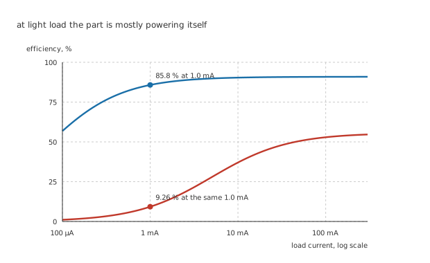
Both curves flatten to the right, where the load is finally large enough to dwarf the part's own appetite.
The quiescent current is what the regulator draws to run its own reference and amplifier, and it does not reach the load at all.
Worked example — The same two parts at 1.0 mA
Drop the load to 1.0 mA and the fixed part is now feeding 5.0 mA of itself and a fifth of that to the load: 9.26 %.
The low-dropout part draws 60 µA, which is a sixteenth of the same load, and manages 85.8 %.
That is a factor of 9.262, at a load current where the fixed part's efficiency figure has stopped meaning anything.
Standing still, the two cost 45.0 mW and 330 µW, a ratio of 136. On a mains-fed board nobody notices. On anything that spends most of its life asleep on a cell, that ratio is the entire design.
Professional
Choosing one, and the two ways it disappoints you
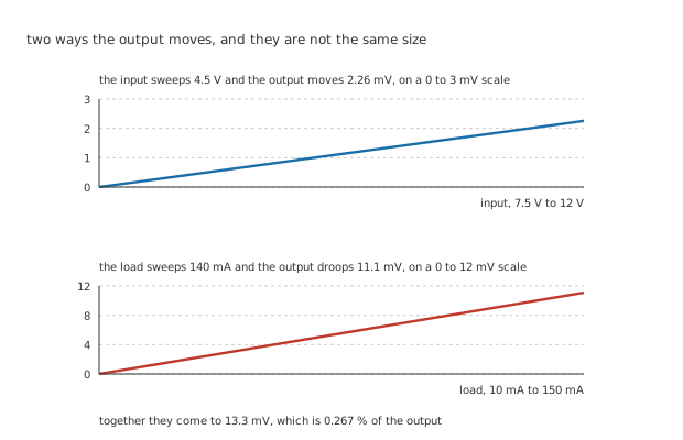
Two scales, because at one scale the upper trace would be fifteen pixels tall.
"Regulated" is a claim with a size. The output moves for two separate reasons and they are not the same size.
Worked example — How steady is steady
The loop rejects input changes by an invented 66 dB. Sweep the input the whole 4.5 V and the output follows by 2.26 mV.
It also has an output impedance: an invented 8.0 Ω of pass-element resistance divided by one plus a loop gain of 100, which is 79.2 mΩ. Sweep the load from 10 mA to 150 mA, its whole 140 mA, and the output droops 11.1 mV.
Together, 13.3 mV — or 0.267 % of the rail.
The load effect is nearly five times the line effect, and that is the usual ordering. It is also why measuring a regulator's output with no load tells you almost nothing.
The input you have is smaller than the input you specified
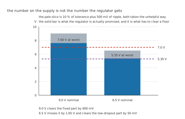
The solid bar is what the regulator is actually promised. The floors are dashed across both.
This is where dropout stops being a specification and becomes a decision.
Worked example — What a nine-volt supply is actually worth
Take 9.0 V nominal with 10 % of tolerance and 500 mV of ripple riding on it, both taken the unhelpful way.
The regulator is promised 7.60 V, which clears the fixed part's 7.0 V floor by 600 mV.
Try the same sum on 6.5 V and the promise is 5.35 V: 1.65 V short of the fixed part, and clearing the low-dropout part by 50 mV.
Fifty millivolts of margin is not margin. It is the number you get before temperature, before the tolerance on the dropout figure itself, and before the day the cell is cold. A part chosen there works on the bench and fails in a fortnight.
The output capacitor is inside the loop
Worked example — Why the datasheet is fussy about it
Put 10 µF on the output with 0.20 Ω of series resistance and the pair has a corner at 79.6 kHz.
Above that corner the capacitor stops looking like a capacitor and starts looking like a resistor, and the loop's phase margin depends on where that happens.
This is the difference between a regulator and a resistor: a regulator has a feedback loop, the capacitor you hang on its output is part of that loop, and swapping it for a better one can make the circuit ring or oscillate. Older parts often want some series resistance and dislike very low values; newer ones usually want the opposite. It is one of the few places where a datasheet's stated range is a hard requirement rather than a suggestion.
When to stop reaching for one
When the heat is the problem. 645 mW has to leave through the package, and whether that is fine or fatal is a thermal question rather than an electrical one.
When the ratio is large. Dropping 12 V to 5.0 V throws away three-fifths of everything drawn. A switching regulator does the same job without the arithmetic of despair, at the cost of noise, an inductor and a layout that has to be thought about.
When the load is small and the battery matters. Then the quiescent current is the specification and the dropout is a detail.
And when it is a rail that has to be quiet. A linear regulator's output noise is low and its rejection of input noise is high, which is exactly why sensitive analogue stages are often fed from one that is itself fed from a switcher. The switcher does the heavy lifting; the linear part cleans up after it, and the volts it wastes are the price of a quiet rail. Getting that rail to the chip without spoiling it is its own discipline.
Common mistakes
- Quoting output over input as the efficiency — that gives 55.6 % here, and counting the 5.0 mA the regulator draws for itself gives 53.8 %. At 1.0 mA of load the same two figures are 55.6 % and 9.26 %, and only one of them is true.
- Choosing a supply without subtracting tolerance and ripple — 6.5 V nominal is 5.35 V at worst, which is 1.65 V short of the 7.0 V a 2.0 V dropout part needs. The bench sample works because the bench supply is exact.
- Treating a low-dropout part as a low-heat part — at 12 V in it manages 41.65 % against the fixed part's 40.3 %, a difference of 1.33 %. The saving comes from being allowed a smaller input, not from the part.
- Sizing the heatsink from the load power — the load takes 750 mW and the regulator dissipates 645 mW, and the second number is the one the package has to survive.
- Changing the output capacitor for a better one — it is inside the feedback loop, and 10 µF with 0.20 Ω puts a corner at 79.6 kHz that the loop's stability was designed around.
- Measuring regulation with no load — the load effect here is 11.1 mV against the line effect's 2.26 mV, so an unloaded measurement misses the larger of the two entirely.
Frequently asked questions
What actually is the pass element?
A transistor, run in its linear region rather than as a switch. The loop drives its base or gate to whatever value makes the divider's tap match the reference, so from the outside it behaves as a resistor that changes value continuously. That is also why it gets hot: a transistor conducting with volts across it is dissipating, and there is no arrangement of a linear regulator in which it is not.
Why is low dropout not simply better?
It usually is, but it is not free. A low-dropout part achieves its small drop with a different pass topology, and that topology tends to be fussier about the output capacitor, slower to recover from a load step, and sometimes noisier. It also has no advantage at all once the input is well above the output, which the efficiency curves show converging within about one per cent by 12 V.
Can I put two in parallel to share the current?
Not directly. Each one is trying to hold its own idea of the output, so the one with the slightly higher setpoint takes the entire load until it hits its current limit and the other never turns on at all. Sharing needs deliberate ballasting or a part built for it, and two ordinary regulators tied together is a way of running one very hot.
Where does the quiescent current go?
Into the reference, the error amplifier and the divider — everything that has to keep running for the loop to hold. It flows from the input to ground and never reaches the load, which is why it costs the full input voltage rather than the drop. Here that is 45.0 mW standing still on the fixed part against 330 µW on the low-dropout one.
What happens if I feed one more input than it is rated for?
Two things, and the second is the one that gets you. The obvious limit is the absolute maximum input the part will survive at all. The quieter one is that dissipation is the drop times the load current, so doubling the headroom doubles the heat with no change to the load, and a part that was comfortable at one input voltage will shut down thermally at another.