
Quick Answer
Feed part of an op-amp's output back to its inverting input and two rules follow. No current flows into the inputs, and the output moves to whatever voltage makes the two inputs equal. Both are approximations, both are extremely good ones, and together they let you read almost any op-amp circuit without arithmetic.
Intuition
The shepherd never touches a sheep
A shepherd wanting the flock in the top field does not carry sheep. They point, and a dog goes and does whatever the situation requires: run wide, lie down, get up, come round the back, hold. The dog is doing all the work and making all the decisions, and none of them were specified.
What the shepherd controls is the outcome. What the dog supplies is effort, in whatever quantity the hill, the weather and the sheep happen to demand today.
Negative feedback is that arrangement in a circuit. You do not tell an op-amp what to do. You arrange things so that the amplifier can see the difference between what you asked for and what is happening, and you connect it so that it acts to shrink that difference. Then you stop thinking about the amplifier.
The reason this works is the absurd gain from the previous lesson. A dog that will run all day makes the shepherd's pointing very precise, because any deviation gets an enormous response. An amplifier with a gain of hundreds of thousands does the same thing: the difference it will tolerate before its output moves a long way is so small that treating it as zero costs almost nothing.
That "almost nothing" has a number, and most of this lesson is spent working out what it is.
Practitioner
Two rules, and a fraction going back where it came from
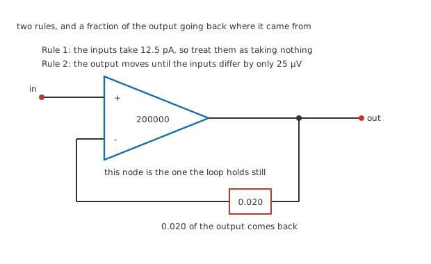
One junction dot, where the feedback branch leaves the output. No resistors, because the fraction is the point and the resistors come later.
Take the amplifier from the previous lesson, unchanged: an invented open-loop gain of 200000, an invented 2.0 MΩ between the inputs and an invented 75 Ω at the output. It belongs to no real part.
Now send a fraction of the output back to the inverting input. Call the fraction 0.020, and leave it abstract for the moment: how you build it is what the next four lessons are about.
Something happens that is easy to miss. The output is now driving its own input, so the amplifier is no longer free to do what its gain says. If the output goes too high, the fed-back share raises the inverting input, which reduces the difference, which pulls the output back down. The circuit settles at whatever output makes the books balance, and it settles there whatever the amplifier's own gain happens to be.
Rule 1: no current goes into the inputs.
Rule 2: the output does whatever it takes to make the two inputs equal.
Neither is true. Both are close enough that the error is invisible in almost every circuit anyone builds, and both come out of the arithmetic rather than being assumed.
Worked example — What the loop settles at
The loop gain is the amplifier's gain multiplied by the fraction coming back: 4000.
Rule 2 predicts a circuit gain of one divided by the fraction, which is 50. The real answer is the amplifier's gain divided by one plus the loop gain, which gives 49.99.
The rule is out by 0.025 %, and that figure is exactly one divided by one plus the loop gain. Nothing else enters it.
The second sentence there is the whole subject. The error the golden rules make is one over the loop gain, near enough, and the loop gain is spare gain you were never going to use anyway.
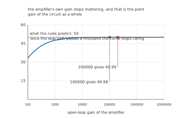
The two marked points are five hundredths of a pixel apart. That is not a drawing problem.
The curve above is what feedback is for. At the left, where the amplifier has almost no gain to spare, the circuit's gain depends heavily on it. By the time the loop gain reaches a few thousand the curve has flattened onto the value the rules predict and stays there.
Engineer
What the rules are actually worth
Worked example — Rule 1, in amperes
With 100 mV in, the output sits at 4.999 V. Working that back through the open-loop gain, the two inputs must actually differ by 25 µV.
Across 2.0 MΩ that difference drives 12.5 pA.
Beside a feedback network carrying 100 µA, the input current is smaller by a factor of 8.0 million. Treating it as zero is not an approximation anyone will catch you making.
Rule 2 comes out of the same line. The inputs are not at the same voltage; they are 25 µV apart, and they have to be, because that difference multiplied by the gain is what produces the output. The "virtual short" is a genuine short as far as any meter you own is concerned, and it is not one in the arithmetic.
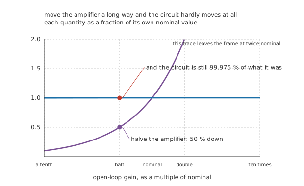
Both traces are fractions of their own nominal value, on one scale that starts at zero.
Worked example — Halve the amplifier
Cut the open-loop gain from 200000 to 100000, a reduction of 50 %.
The circuit's gain moves from 49.99 to 49.98, a change of 0.025 %. The circuit still delivers 99.975 % of what it delivered before.
The amplifier moved 2001 times as far as the circuit did.
That ratio is the argument. Open-loop gain varies between parts from the same reel, falls as the part warms up, and drops steadily with frequency. A circuit whose behaviour depended on it would be unbuildable. A circuit that spends it instead is one you can design on paper.
The loop moves both ends the way you want
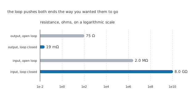
Log scale, so the bar lengths are logarithms and are not offered as proportions.
There is a second dividend, and it arrives without being asked for.
An output that is being corrected cannot sag under load, because sagging raises the difference at the inputs and the amplifier answers by pushing harder. The 75 Ω of the bare part becomes 19 mΩ at the circuit's output terminal.
The same factor works upwards at the input. A source driving the non-inverting input sees the difference across 2.0 MΩ held near zero, so it is asked for almost no current at all, and the effective resistance rises to 8.0 GΩ.
Both are divided or multiplied by one plus the loop gain, which is 4000 plus one here. The same number that shrank the gain error moved both impedances, because it is the same loop doing all three jobs.
Professional
Where the rules stop being safe
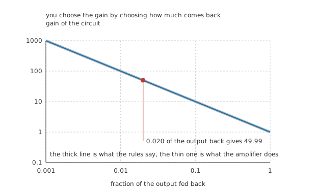
The thick line is the prediction, the thin one is the delivery. They are the same line over most of the range.
The golden rules are an approximation with a condition attached, and the condition is that there is plenty of loop gain. Ask for too much gain from the circuit and there is not.
Demanding a circuit gain of a thousand from an amplifier with 200000 leaves a loop gain of only two hundred, and the delivered gain falls visibly short of the prediction. That is the left edge of the figure, and it is the same effect that made the left edge of the earlier curve rise so steeply: the rules and the amplifier are the same thing seen from two directions.
The practical test is not the gain you asked for. It is what is left over.
Worked example — How much loop gain is enough
With the fraction at 0.020, the loop gain is 4000 and the rules are out by 0.025 %.
Halve the amplifier and the loop gain halves too, so the error doubles to 0.050 %.
An error budget is therefore a loop-gain budget. Decide what you can tolerate, invert it, and that is the loop gain the design needs at the worst amplifier, the worst temperature and the highest frequency it has to work at.
And the sign, which is not negotiable
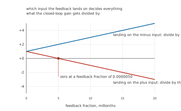
Two straight lines. The one that crosses zero is the one that does not make an amplifier.
Everything above assumed the feedback lands on the inverting input. Land it on the other one and the sign in the denominator changes, and the arithmetic stops describing an amplifier.
With the same fraction, the denominator becomes -3999. A negative divisor does not mean the circuit has negative gain; it means the algebra has left the region where it applies. What the circuit actually does is run to a rail and stay there, because now any drift away from balance is reinforced rather than opposed.
The crossing happens at a feedback fraction of 0.0000050, which is one divided by the open-loop gain. Above that, positive feedback latches. Below it, the loop is too weak to hold and the circuit merely has a slightly odd gain.
This is not a failure mode to be avoided everywhere. It is a circuit in its own right, and a very useful one, which is what comparators and hysteresis are about. Deployed by accident it is a fault; deployed on purpose it is how you stop a noisy signal from making the output chatter.
What to carry forward
Read the circuit, not the amplifier. Assume the inputs are equal and draw no current, work out what the output must be for that to hold, and you have the answer.
Then check the loop gain. If it is in the thousands the assumption is worth 0.025 %. If it is in the tens, do the arithmetic properly.
The feedback must land on the inverting input. Every circuit in the next four lessons does this, and the one lesson that does otherwise says so loudly.
None of this is about speed yet. Loop gain falls with frequency, and everything the rules buy you falls with it. That is real op-amp limitations, and it is where the tidy picture ends.
Common mistakes
- Believing the inputs are actually at the same voltage — they differ by 25 µV here, and they must, because that difference multiplied by 200000 is what produces the 4.999 V output. The virtual short is a very good approximation and not an identity.
- Quoting the ideal gain when the loop gain is small — 1 divided by the feedback fraction gives 50, and the circuit delivers 49.99. That 0.025 % is fine. Ask the same amplifier for a gain of a thousand and the loop gain drops to two hundred, and the shortfall stops being ignorable.
- Treating open-loop gain as a design parameter — halving it from 200000 to 100000, a change of 50 %, moves the circuit by 0.025 %. If your answer depends on the amplifier's own gain, the loop gain is too low.
- Feeding back to the wrong input — with the same fraction the denominator becomes -3999, which is the arithmetic saying it has stopped describing an amplifier. The output goes to a rail and stays there.
- Forgetting rule 1 is about current, not resistance — the inputs draw 12.5 pA here, which is 8.0 million times less than the 100 µA in the feedback network. That ratio, not the 2.0 MΩ, is why the rule holds.
- Expecting the improved impedances for free at any frequency — the output resistance falls to 19 mΩ and the input rises to 8.0 GΩ because the loop gain is 4000. Both figures degrade exactly as the loop gain does.
Frequently asked questions
If the two inputs are not really equal, how can the rule be safe to use?
Because the difference is set by the output divided by the open-loop gain, and that is tiny. Here the output is 4.999 V and the gain is 200000, so the inputs sit 25 µV apart. Any circuit whose behaviour would change if that were zero instead is a circuit with too little loop gain, and the fix is more loop gain rather than a better rule.
What exactly is loop gain?
The gain all the way round the loop: the amplifier's own gain multiplied by the fraction of the output that comes back. Here that is 200000 times 0.020, which is 4000. It is the quantity that decides how good the golden rules are, how far the impedances move, and how much of the amplifier's imperfection the circuit hides.
Why does feedback lower the output resistance?
Because the amplifier is watching the output, not the source. If a load pulls the output down, the difference at the inputs grows, and the amplifier drives harder until the output is back where the feedback says it should be. The correction happens for the same reason and by the same factor as everything else the loop does, which is why 75 Ω becomes 19 mΩ.
Does more feedback always mean a better circuit?
More loop gain means a more accurate one, and loop gain is set by both the amplifier and the fraction fed back. Asking for less gain from the circuit leaves more loop gain over, which is why a unity-gain stage is the most accurate configuration available and a high-gain stage is the least. What limits it in practice is frequency, and that arrives in a later lesson.
Are the golden rules exact for an ideal op-amp?
Yes, and that is what "ideal" means: infinite gain makes the input difference exactly zero and infinite input resistance makes the input current exactly zero. Real parts have neither, so the rules acquire an error of one over the loop gain. Working with the ideal rules and then checking the loop gain is the normal way to design, and it is faster than working exactly and then simplifying.