
Quick Answer
Put an op-amp inside a filter and three things change. The stages stop loading each other, so cascading works. The circuit can have gain instead of only loss. And feeding some output back through a capacitor sharpens the corner far more than passive components alone can, with no inductor anywhere.
Intuition
A sieve with gain
A sieve does one job. Everything smaller than the mesh goes through, everything larger stays behind, and the sieve itself contributes nothing but the obstacle. Whatever comes out the bottom is a subset of what went in, always less, never more.
Stack two sieves and you get a better sort, but you also get a slower one: the second sieve holds up the flour that has cleared the first, and the pile above it changes how the first one behaves. Sifting is a job you can only make worse by doing more of it in one pass.
A passive filter has both of those properties. It only ever takes away, and putting two of them in a row makes each of them work less well than it did alone.
Now imagine a sieve with somebody standing under it, catching what comes through and passing it on with a shovel. The second sieve never feels the first one. Whatever it receives arrives with as much force as you like, so the stages are independent, and if you want more out than went in you can have it.
That is what an op-amp does to a filter. The gain is the least of it. The important part is that the stages stop talking to each other, and the interesting part is what happens when you send a little of the shovelled output back up to the mesh.
Practitioner
One order, and then two
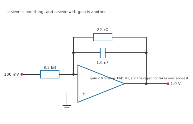
Four junction dots. The capacitor across the feedback resistor is the entire filter.
Start with the simplest one. Take an inverting amplifier and put a capacitor across the feedback resistor.
At low frequencies the capacitor passes almost nothing and the gain is what the two resistors say. At high frequencies the capacitor is a much easier path than the resistor, so the effective feedback impedance falls and the gain falls with it. The corner is where the two paths are equally easy.
Worked example — One resistor, one capacitor, one corner
An invented stage: 8.2 kΩ in, 82 kΩ back, and 1.0 nF across the feedback resistor.
100 mV drives 12.2 µA through the input resistor, and in the passband all of it goes through 82 kΩ, giving a gain of -10.0 and an output of 1.0 V.
The corner is at 1941 Hz, which is not a round number because 82 kΩ and 1.0 nF are ordinary stock values.
That is a real filter with real gain, and it needed one extra component. A passive network can do the corner but not the gain, and this arrangement does both from the same two parts. Every figure in this lesson is invented and belongs to no real design.
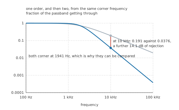
Both normalised to their own passbands, so the comparison is about shape.
What it cannot do is fall steeply. One capacitor gives one order of filtering, and beyond the corner the response falls in proportion to frequency and no faster. The generic picture of that slope belongs to its own lesson; what matters here is that ten times past the corner leaves a tenth of the signal, and often that is not enough.
Engineer
The capacitor that goes back to the output
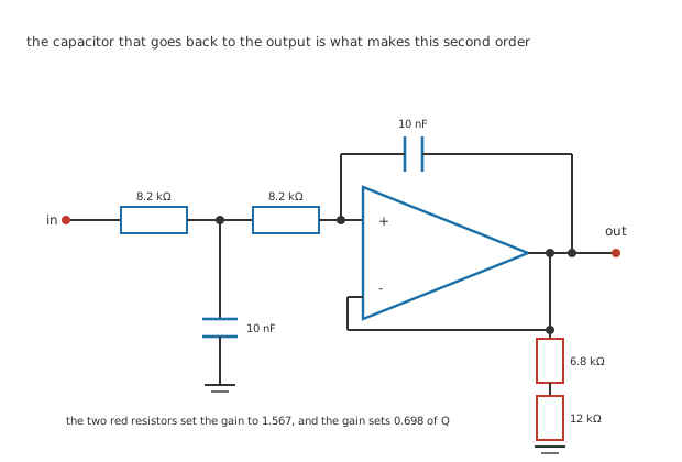
Four junction dots. The second capacitor returns to the amplifier's output rather than to ground.
Here is the arrangement that made active filters worth having. Two resistors in series from the input to the amplifier's non-inverting terminal, one capacitor from the midpoint to ground, and a second capacitor from the amplifier's output back to that same midpoint.
The second capacitor is what makes this different from two passive sections in a row. Near the corner the amplifier's output is still nearly as large as the input, so the capacitor going back to it carries very little current, which leaves the midpoint less loaded than it would otherwise be and holds the response up. Above the corner the output has fallen away, the returned capacitor stops helping, and the response drops at twice the first-order rate.
Worked example — Where the corner is and how sharp it is
Both resistors are 8.2 kΩ and both capacitors 10 nF, so the corner is at 1941 Hz — the same corner as the first-order stage, chosen so the two can be compared.
The divider of 6.8 kΩ over 12 kΩ sets the amplifier's gain to 1.567.
With equal components the Q is one divided by three minus that gain, which is 0.698. Nothing else in the circuit affects it.
Worked example — What the second order is worth
At 10 kHz, five times the corner, the first-order stage passes 0.191 of its passband, which is -14.4 dB.
The second-order stage passes 0.0376, which is -28.5 dB.
That is 14.1 dB further down, or 5.07 times less signal, from two extra passive components and no extra amplifier.
Professional
Two resistors nobody looks at
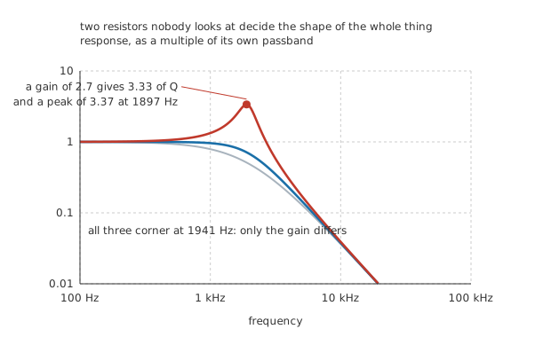
Same resistors, same capacitors, same corner. Only the amplifier's gain differs.
The Q of an equal-component Sallen-Key comes from the amplifier's gain and from nothing else. Change the gain-setting divider and the shape of the response changes while the corner stays exactly where it was.
Worked example — What too much gain does
Raise the amplifier's gain to 2.7 and the Q rises to 3.33.
The response now peaks at 1897 Hz, just below the corner, where it reaches 3.37 times the passband.
That is 10.6 dB of gain the design did not ask for, applied to whatever happens to be at that frequency.
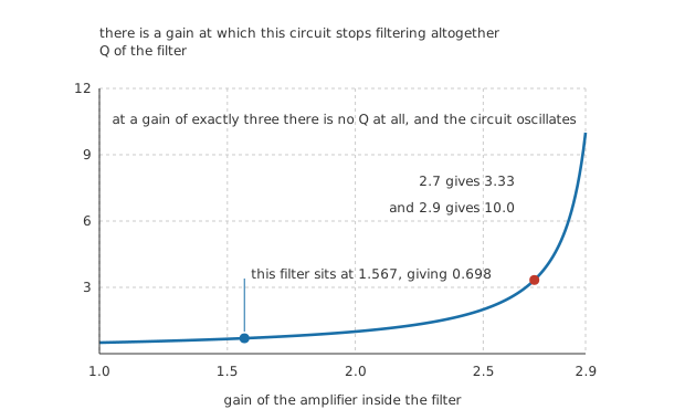
Slowly, and then all at once. The wall is at a gain of exactly three.
Follow that curve to its end and the arithmetic says something alarming. At a gain of exactly three the Q is one divided by zero, which is not a very sharp filter but a circuit that produces an output with no input at all. It has become an oscillator, and building one deliberately on that principle is a lesson later in this department.
So the two resistors setting the amplifier's gain are the most critical components in the filter. They do not appear in the corner frequency, they are usually drawn small and off to one side, and a designer choosing them casually can turn a flat response into a peaked one or a filter into an oscillator. Everything the inverting amplifier lesson said about matching and drift applies to them with much more force.
And the reason all of this works at all
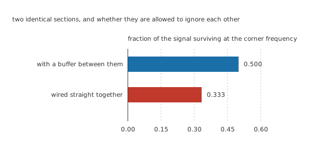
One scale through zero. The difference is what the second section takes from the first.
Worked example — Why two passive sections are not twice as good as one
Two identical RC sections, each with the same corner. Buffered from each other, each does its own job and 0.500 of the signal survives at that corner.
Wired straight together, the second section draws current from the first and loads it. Only 0.333 survives.
That is 3.52 dB lost to nothing but the two stages being able to see each other, and it gets worse with every section added.
An op-amp's output resistance, once the loop has closed round it, is milliohms. A stage driven from one and loaded by another sees nothing at all, so a four-pole filter really is two two-pole filters in a row, and each can be designed on its own. Passive filters cannot be designed that way, which is why the tables for them are so much more complicated.
What to take away
Active filters have no inductors. That is why they exist below a few hundred kilohertz, where an inductor with a useful value is large, lossy and expensive.
The corner comes from the resistors and capacitors; the shape comes from the amplifier's gain. Two separate design decisions, and they do not interact.
Cascade freely. Two second-order stages give a fourth-order filter, and neither stage knows the other is there.
And nothing here is true at speed. Every calculation assumed the amplifier is ideal, which stops being a safe assumption when the filter's corner approaches the amplifier's own limits. Real op-amp limitations is where that gets settled.
Common mistakes
- Choosing the gain-setting divider casually — in an equal-component Sallen-Key the Q is one over three minus the gain, so 1.567 gives 0.698 and 2.7 gives 3.33. Those two resistors do more to the response than either capacitor does.
- Building a filter with a gain of three — the Q becomes one divided by zero, and the circuit oscillates rather than filtering. Approach it and the peaking gets steadily worse: 2.9 already gives a Q of 10.0.
- Expecting two cascaded passive sections to behave like two independent ones — they do not, because the second loads the first. At the corner a buffered pair passes 0.500 and a directly coupled pair only 0.333, a loss of 3.52 dB before any design error.
- Assuming a first-order stage is enough — at 10 kHz against a 1941 Hz corner it passes 0.191 where the second-order stage passes 0.0376. That is 14.1 dB, from two extra passive components.
- Reading the corner off the wrong components — the corner is 1941 Hz from the 8.2 kΩ and 10 nF, and the gain divider does not appear in it at all. Changing the gain moves the shape, not the corner.
- Treating the amplifier as ideal at any frequency — everything in this lesson assumes it is, which holds while the corner is far below the amplifier's own limits and stops holding when it is not.
Frequently asked questions
Why does an active filter not need inductors?
Because the second capacitor returning to the amplifier's output does the job an inductor would have done: it provides the second energy storage element and the phase relationship that a second-order response needs. Below a few hundred kilohertz that is a very good trade, because inductors of useful value are physically large, have resistance of their own, and pick up interference. Above that the trade reverses.
Does the Q always come from the amplifier's gain?
In the equal-component Sallen-Key, yes. Other arrangements put it elsewhere: a unity-gain Sallen-Key with unequal capacitors sets Q from the ratio of the two capacitors instead, and multiple-feedback topologies set it from a combination of resistors. What is always true is that Q comes from somewhere specific, and finding where before you change anything is the first job.
Is a peaked response ever what you want?
Sometimes. Higher-order filters are built from cascaded second-order stages with deliberately different Q values, and some of those stages peak on their own while the cascade as a whole is flat. What you do not want is peaking you did not design, which is what a casually chosen gain divider produces.
How high can the corner frequency go?
Until the amplifier stops being able to keep up, which for the filter is when the loop gain at the corner stops being large. Rules of thumb put the practical ceiling one or two decades below the amplifier's unity-gain frequency, and above that the filter's actual response departs from the design in ways the calculation does not predict.
Can I make a high-pass filter the same way?
Yes: swap the resistors and capacitors in the Sallen-Key and the same arithmetic gives a high-pass with the same corner and the same Q from the same gain. Band-pass and band-stop follow from combinations. The topology is a framework rather than one circuit, which is most of why it is used so widely.