
Quick Answer
A real op-amp's open-loop gain falls in proportion to frequency, so every circuit built on it has a bandwidth set by the gain it was asked for. Its output has a separate speed limit that depends on amplitude rather than gain. And its inputs carry an offset and a bias current that produce an output error before any signal arrives.
Intuition
The blanket is too short
There is an amount of blanket, and it does not change. Pull it up over your shoulders and your feet come out. Cover your feet and your shoulders are cold. Tuck it round the sides and there is less of it going lengthways. Nobody is doing anything wrong, and there is no arrangement that solves it, because the difficulty is not in the arranging.
Every lesson so far has spent the op-amp's gain freely, on the understanding that there was always plenty. There was, at direct current. There is not at any speed worth mentioning, and the amount available at a given frequency is fixed by the part.
That is the shape of this lesson, and it applies twice over. There is a fixed amount of gain to divide between accuracy and bandwidth. There is a fixed rate at which the output can move, to be divided between amplitude and frequency. And underneath both there is a set of errors that do not scale with anything and are simply there.
The circuits in the last eight lessons all still work. What changes is that each of them now has a frequency above which it stops doing what it was designed to do, and that frequency is usually a great deal lower than the one on the front of the datasheet.
Practitioner
All the spare gain, and where it runs out
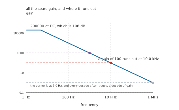
The gap between a closed-loop line and the roll-off is the loop gain at that frequency.
The amplifier's own gain is not a number. It is a number at direct current and a falling curve after that.
The batch's invented amplifier has an open-loop gain of 200000, which is 106 dB, and a gain-bandwidth product of 1.0 MHz. Those two together fix everything in this layer, because the product is what stays constant: above a corner the gain and the frequency trade one for one.
Worked example — Where the corner is, and what a circuit gets
The open-loop gain stops being flat where the falling line reaches it, which is the product divided by the gain: 5.0 Hz.
A circuit built for a gain of 100 runs out where the roll-off falls to that value, at 10.0 kHz.
A follower gets the whole 1.0 MHz, which is the product itself, and is another reason a follower is the best-behaved configuration there is.
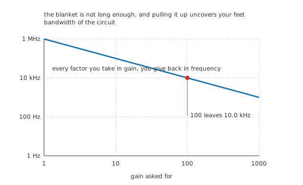
A straight line of slope minus one, because the product is what is fixed.
That is the blanket. Every factor of gain you take is a factor of bandwidth you give back, and the two multiply to the same number whatever you do. Every figure in this lesson is invented and belongs to no real part.
The generic picture of a falling response belongs to its own lesson, which already carries an illustrative op-amp roll-off and hands off here by name. What this lesson adds is what the falling gain does to the circuits built on it.
Engineer
The accuracy goes first
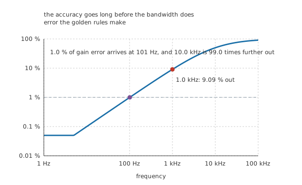
Both axes logarithmic, because the error covers four decades before the bandwidth is anywhere near.
Here is the part that surprises people, and it is the most useful thing in the lesson.
The golden rules are out by one over the loop gain, and the loop gain is the open-loop gain divided by the gain asked for. Both terms are now frequency-dependent, so the error is too.
Worked example — How wrong the gain is on the way up
At direct current the loop gain is 200000 over 100, so the rules are out by 0.050 %.
At 1.0 kHz the open-loop gain has fallen to a thousand, so the loop gain is ten and the rules are out by 9.09 %. That is 182 times worse, at a frequency well inside the stated bandwidth.
The 1.0 % a design might allow arrives at 101 Hz, which is 99.0 times below the 10.0 kHz a datasheet calls the bandwidth.
The bandwidth is where the gain is 30 % wrong, not where it is right. A circuit specified to its stated bandwidth is a circuit specified to a gain error of about half, and nobody means that. What a design actually has is the frequency at which the error reaches whatever it can tolerate, and that is a factor of a hundred lower here.
The fix is the same as everywhere else in this department: leave more loop gain. Ask for less gain per stage, use two stages instead of one, or use a faster amplifier. All three are the same decision seen from different sides.
Professional
A different ceiling, on a different quantity
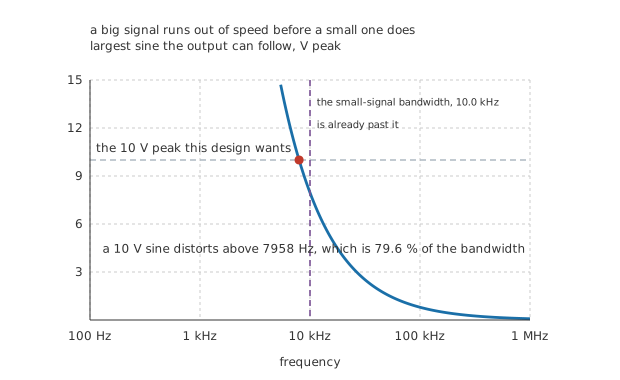
The vertical rule is the small-signal bandwidth, and it arrives after the crossing.
Everything above concerns small signals. There is a second limit that has nothing to do with gain at all.
An op-amp's output cannot change faster than a certain rate, whatever the feedback demands, because internally a fixed current is charging a fixed capacitor. That rate is the slew rate, an invented 0.50 V/µs here, and it caps the product of amplitude and frequency rather than gain and frequency.
Worked example — When a large signal stops being a sine
A sine of 10 V peak needs its steepest part to move at two pi times the frequency times the amplitude.
Set that equal to the slew rate and the largest frequency at which the output can keep up is 7958 Hz.
At the 10.0 kHz the small-signal bandwidth allows, the output can only follow 7.96 V. The full-power limit is 79.6 % of the bandwidth, so a large signal distorts before a small one is even attenuated.
The failure looks different too. Falling gain makes a signal smaller and leaves its shape alone. Slew limiting turns a sine into a triangle, which is not a smaller sine at all but a different signal with harmonics in it that were never present at the input.
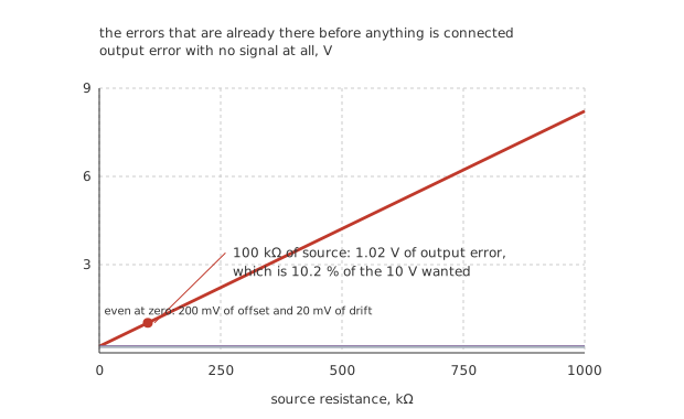
Three stacked traces. Two of them are flat, and neither goes away.
And the errors that arrive with nothing connected
Worked example — What the output reads with the input grounded
An invented input offset of 2.0 mV looks exactly like a real input, so at a gain of 100 it puts 200 mV at the output.
Warming the part by 40 °C at 5.0 µV/°C adds 200 µV to that offset, which is 20 mV more at the output.
And 80 nA of bias current through a 100 kΩ source is 8.0 mV, which is 800 mV more again.
The three add to 10.2 mV at the input and 1.02 V at the output, which is 10.2 % of the 10 V the design wanted.
Notice which term won. The offset is the one everyone worries about and the bias current through a high source resistance is four times larger. Lowering the source resistance is usually easier than finding a better-trimmed amplifier, and it is the first thing to try.
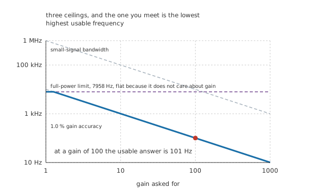
The thick trace changes hands at a gain of 1.27. Below that the slew rate binds; above it, the accuracy does.
Putting the three together
Worked example — What this stage can actually do
The small-signal bandwidth at a gain of 100 is 10.0 kHz.
The 10 V output the design wants runs out of slew rate at 7958 Hz, and that limit does not care about the gain at all.
The 1.0 % of gain error the design allows arrives at 101 Hz. The lowest of the three is the answer, and it is that last one.
Which of the three binds depends on the gain, and the changeover is at 1.27. Below that the slew rate is the limit even at unity gain, which is why a follower asked for a large fast signal disappoints; above it the accuracy is, and it stays the binding one for every gain a real circuit uses.
None of the three is the number on the datasheet's front page. That number is the gain-bandwidth product, and it is a property of the amplifier rather than of anything you build with it.
Common mistakes
- Designing to the closed-loop bandwidth — at a gain of 100 that is 10.0 kHz, and the gain is already 1.0 % out at 101 Hz, a factor of 99.0 lower. The bandwidth is where the answer is about half wrong.
- Assuming slew rate and bandwidth are the same limit — they are not, and the slew one does not depend on gain. A 10 V sine distorts above 7958 Hz whatever the circuit's gain is, which is 79.6 % of this stage's small-signal bandwidth.
- Worrying about the offset and ignoring the bias current — 2.0 mV of offset gives 200 mV at the output, and 80 nA through a 100 kΩ source gives 800 mV. The one nobody specifies is four times the one everybody does.
- Taking all the gain in one stage — 100 in one stage leaves 10.0 kHz; two stages of ten leave 100 kHz each, and the accuracy limit moves up with it. The arithmetic favours splitting almost always.
- Reading the gain-bandwidth product as a bandwidth — 1.0 MHz is what a follower gets. Everything else divides it, and then the accuracy requirement divides it again.
- Forgetting the drift — 5.0 µV/°C over 40 °C adds 200 µV to the offset, which is 20 mV at the output. Small against the other terms here and dominant in a circuit whose offset has been trimmed out at one temperature.
Frequently asked questions
Why does the open-loop gain fall at all?
On purpose. A capacitor inside the amplifier deliberately puts one pole far below everything else, so the response is a single falling slope across the whole useful range and the phase never accumulates enough to make a feedback loop unstable. The falling gain is the price of being able to close a loop round the part at all, and an uncompensated amplifier is faster and much harder to use.
How do I get more bandwidth at the gain I need?
Split the gain. Two stages of ten give a gain of a hundred with each stage running at 100 kHz instead of one stage at 10.0 kHz, and the accuracy limit rises in proportion too. It costs another amplifier, more offset and more noise, and it is usually still the right trade. The alternative is a part with a larger gain-bandwidth product, which costs more supply current.
Is slew limiting the same as clipping?
No. Clipping is the output reaching a rail and stopping; slew limiting is the output moving as fast as it can and still not keeping up, which turns a sine into a triangle without ever touching a rail. They can happen together and they look different on an oscilloscope: clipping has flat tops, slew limiting has straight sides.
Can I cancel the bias current error?
Partly. Making the resistance seen by both inputs equal makes both bias currents produce the same error, which then cancels as a common-mode input, and what is left is the mismatch between them. That mismatch has its own name, the input offset current, and is usually a small fraction of the bias current. It does nothing about the offset voltage, which needs a trim or a better part.
Which limitation matters most in practice?
Whichever one your circuit meets first, and that depends on what it is for. A precision DC amplifier is limited by offset, bias and drift and never notices the bandwidth. An audio stage is limited by slew rate on large signals. A control loop is limited by the accuracy falling with frequency long before either. The first job in a design is working out which of the three you are in.