
Quick Answer
Feed the signal straight into the non-inverting input and tap a divider from the output back to the inverting one. The op-amp raises its output until the tap matches the input, so the gain is one plus the ratio of the two resistors. It cannot go below one, and the input draws almost nothing.
Intuition
The shadow is never smaller
Hold your hand between a lamp and a wall and the shadow on the wall is a copy of it: the same way up, the same shape, and bigger. How much bigger depends only on the two distances, the lamp to your hand and your hand to the wall. Move the wall further away and the shadow grows.
Two things about that arrangement are worth noticing before the circuit arrives.
The shadow is always at least as big as the hand. There is no way to arrange a lamp, a hand and a wall that makes the shadow smaller, because the light spreads. And casting the shadow costs your hand nothing: no effort is transferred, the lamp does all the work, and your hand would be doing exactly the same thing if the wall were not there.
The non-inverting amplifier has both properties, and they are the two things worth knowing about it. Its gain can never be less than one, and the source driving it is asked for essentially nothing. The first is a genuine restriction. The second is the reason the circuit exists.
Practitioner
The signal goes in the front
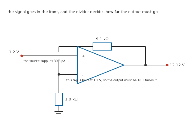
Two junction dots, and one deliberate break where the input run crosses the tap column without joining it.
The signal goes directly to the non-inverting input, and nothing else connects there. A divider hangs off the output: 9.1 kΩ from the output down to the inverting input, and 1.0 kΩ from there to ground.
The op-amp is the same invented part the batch has used throughout — an open-loop gain of 200000, 2.0 MΩ between the inputs, an output reaching 13.5 V, and inputs that accept 12 V either way. Every figure in the lesson is invented and belongs to no real part.
Now apply the second golden rule. The op-amp will move its output until the two inputs are equal, and the inverting input is the divider's tap, so the output goes to whatever voltage puts the tap at the input voltage.
Worked example — Working out the gain from the divider
The divider passes 0.0990 of the output down to the tap.
The loop holds the tap at 1.2 V, so the output has to be that divided by the fraction: a gain of 10.1, giving 12.12 V.
Which is one plus the ratio of the two resistors, and is the same statement written the other way round.
Note the gain is 10.1 and not ten. 9.1 kΩ and 1.0 kΩ are ordinary stock values, and the ordinary stock values do not give round gains. You can chase a round number with a series pair or a trimmer, and most of the time nobody bothers, because the specification is usually "about ten" and the circuit is asked to be repeatable rather than round.
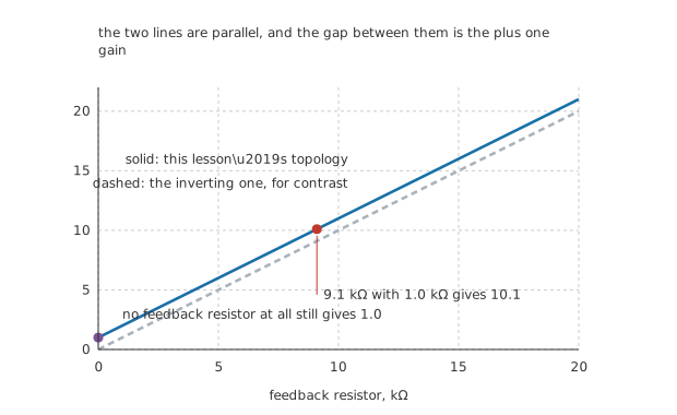
The vertical gap is one unit of gain everywhere on the axis, which is what the plus one means.
Where the plus one comes from
The extra one is not a correction bolted on. It is there because the signal itself reaches the output through the amplifier, on top of whatever the divider ratio asks for.
Set the feedback resistor to zero and the divider passes all of the output to the tap, so the output has to equal the input: a gain of 1.0. That is the floor, and no arrangement of the two resistors gets below it. A non-inverting amplifier cannot attenuate. If you want a gain of a half, this topology has nothing to offer and the inverting one does.
Engineer
What the source is asked for
Worked example — How little the input takes
The output sits at 12.12 V, so the difference between the inputs is that divided by 200000, which is 60.6 µV.
Across the amplifier's 2.0 MΩ that draws 30.3 pA.
Seen from the source, the circuit's input resistance is 2.0 MΩ multiplied by one plus the loop gain: 39.6 GΩ.
The last figure is not a number to design with. Long before it means anything the real limits are the amplifier's leakage, the resistance across the board and the resistance of the air, and a datasheet quotes a common-mode input resistance that is far lower and much more honest. What the calculation does say correctly is that this topology asks the source for nothing that matters.
That is the whole difference from the inverting circuit, which loads its source with the input resistor and cannot help it.
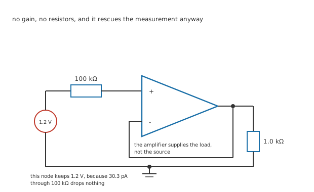
No resistors at all in the feedback path, which is what makes the gain exactly one.
The follower
Take the feedback resistor away entirely and wire the output straight to the inverting input. The gain is 1.0, the circuit does nothing to the signal, and it is one of the most useful things an op-amp does.
Worked example — What the follower is worth
A source with 100 kΩ of its own resistance drives a 1.0 kΩ load directly. The two form a divider, so the load receives 11.88 mV of the 1.2 V available.
That is 99.01 % of the signal gone, in a connection nobody drew as a divider.
Put a follower between them and the source supplies 30.3 pA, drops nothing across its own resistance, and the load gets all of it.

The flat trace is the buffered case. The falling one is the same source connected straight through.
This is why followers turn up in front of every high-impedance sensor, every potentiometer used as a reference, and every point in a circuit where something with no strength has to drive something that wants current. The circuit contributes no gain and no filtering and no cleverness. It contributes the ability to supply current, which the source did not have.
Professional
What it costs
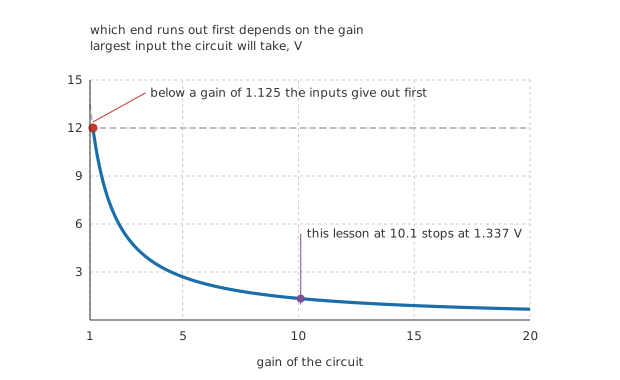
Two dashed constraints and the thick trace of whichever is smaller.
There is a cost to putting the signal on the non-inverting input, and it is easy to miss because it does not show up as a resistor.
In an inverting amplifier both inputs sit at ground whatever the signal does. Here they sit at the signal, and they move with it. Two consequences follow, and the first one is a hard limit.
Worked example — Which end gives out first
The inputs accept 12 V either way. The output reaches 13.5 V, which at a gain of 10.1 corresponds to an input of 1.337 V.
Whichever is smaller is the real limit, and they swap over at a gain of 1.125.
So a follower is limited by its inputs and every useful amplifier is limited by its output, and the crossover is barely above unity.
The second consequence is subtler. An op-amp does not reject its common-mode input perfectly, and here the common-mode input is the signal.
Worked example — What imperfect rejection costs here
Give the part an invented common-mode rejection of 90 dB, which as a ratio is 31623.
At 1.2 V of common-mode input, that appears as 37.9 µV of apparent input error, which the gain turns into 383 µV at the output.
Against 12.12 V that is 0.0032 %, so it matters here and it would matter enormously if the signal were small and the common-mode swing were large. Instrumentation amplifiers are built around exactly that case.
An inverting amplifier is immune to all of that, because its inputs never move.
The compensation nobody expects
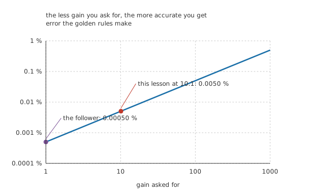
A straight line of slope one, because the error is the gain divided by the open-loop gain.
Worked example — Why the follower is the most accurate circuit there is
At a gain of 10.1 the loop gain is 19802, so the golden rules are out by 0.0050 %.
A follower feeds back the whole output, so its loop gain is the full 200000 and the error falls to 0.00050 %.
That is 10.1 times better, and no configuration of any op-amp does better than a follower, because none can feed back more than all of the output.
Reading one on a schematic
The signal arrives at the non-inverting input. That alone identifies the topology, before you look at any resistor.
The gain is one plus the divider ratio, and the divider is the one hanging off the output, not the one at the input.
No feedback resistor at all means a follower. Gain of exactly one, and the most accurate circuit in the book.
Check the common-mode range before the output range. At low gain the inputs give out first, and the crossover is at a gain of 1.125.
Common mistakes
- Forgetting the plus one — a 9.1 kΩ over 1.0 kΩ divider gives a gain of 10.1, not 9.1. The extra one is the signal reaching the output through the amplifier itself, and it is there in every non-inverting circuit.
- Trying to attenuate with this topology — the gain floor is 1.0 and no pair of resistors gets below it. Attenuation needs the inverting circuit, or a divider in front of this one.
- Quoting the closed-loop input resistance as a design figure — 39.6 GΩ is what the arithmetic gives and it is not what the part does. Leakage, board resistance and the datasheet's own common-mode input resistance all arrive far sooner.
- Ignoring the common-mode range — the inputs move with the signal here, and they accept only 12 V. Below a gain of 1.125 that limit binds before the output's 13.5 V does, which makes the follower the case where it matters most.
- Assuming common-mode rejection never matters — at 90 dB and 1.2 V of signal, 37.9 µV of apparent input error becomes 383 µV at the output. That is 0.0032 % here and would be far worse with a small signal riding a large common-mode swing.
- Thinking a follower does nothing — it turns a source that could deliver 11.88 mV of a 1.2 V signal into one that delivers all of it. The circuit supplies no gain and rescues 99.01 % of the measurement.
Frequently asked questions
Why can the gain never go below one?
Because the signal reaches the output through the amplifier as well as through whatever the divider ratio asks for. Setting the feedback resistor to zero makes the divider pass all of the output to the tap, so the output must equal the input exactly. There is nothing further to remove, and the gain of 1.0 is a floor rather than a limit of the components.
Is the input resistance really tens of gigohms?
The arithmetic says 39.6 GΩ, and no. Long before that number means anything you meet leakage across the board, the amplifier's own input current, moisture on the surface and the resistance of the air. What the figure does say correctly is that the source is asked for 30.3 pA, which for most sources is the same as nothing.
Why does the common-mode range matter here but not in an inverting amplifier?
Because the inputs move with the signal. An inverting amplifier holds both of its inputs at ground however large the signal gets, so the common-mode range is never approached and the amplifier's rejection of it never matters. Here both inputs sit at the input voltage, which is where the 12 V limit and the 90 dB of rejection both start to bite.
Should I use a follower or just connect things directly?
Connect directly when the source can supply the current, which usually means the source resistance is much smaller than the load. When it is not, the divider they form takes the signal: 100 kΩ into 1.0 kΩ loses 99.01 % of it. A follower costs one op-amp and one supply, and removes the question entirely.
Why are the resistor values not chosen to give a round gain?
Because ordinary stock values do not give round gains, and pretending otherwise teaches the wrong lesson. 9.1 kΩ over 1.0 kΩ is a stock pair and it gives 10.1. If the gain must be exact you use a series combination, a trimmer, or a matched resistor network; most designs simply do not need it, and specify the tolerance rather than the value.