
Quick Answer
An instrumentation amplifier puts a buffer in front of each input of a difference amplifier and sets the whole gain with one resistor. Because the sources never touch the matched resistor network, their own resistance cannot unbalance it, and the common-mode rejection survives contact with a real sensor.
Intuition
The spirit level
A spirit level tells you one thing and refuses to tell you anything else. Rest it on a table and it reports whether one end is higher than the other. Lift the whole table by a metre and the bubble does not move. Put the level on a shelf, a roof or the deck of a ship, and it reports the same difference from the same reading, because the height of the whole thing was never part of the question.
That refusal is what makes it an instrument. A level that drifted a little when you carried it upstairs would be useless, not because the drift is large but because you would never know how much of the reading was the slope and how much was the staircase.
Measurement circuits have the same problem in electrical form. A sensor at the end of a cable produces a small difference riding on whatever the supply, the ground system and the cable have done to the common level, and the difference is what you want. The previous lesson's difference amplifier does the job in principle and is defeated in practice by something very ordinary: the sensor has resistance of its own.
An instrumentation amplifier is the arrangement that fixes it, and the fix is simpler than the circuit looks.
Practitioner
The two inputs never touch a resistor
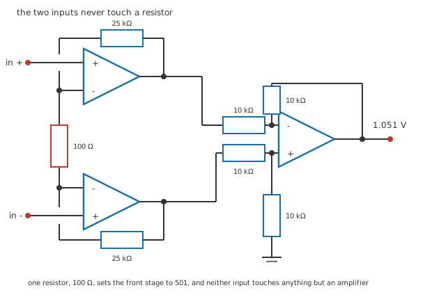
Seven junction dots, and two deliberate breaks where the gain-resistor column crosses the input runs.
Look at where each input goes. It arrives at the non-inverting terminal of its own amplifier and stops. Nothing else connects there: no resistor to ground, no resistor to anything, nothing that could form a divider with whatever resistance the source happens to have.
That single fact is the whole design. Everything else follows.
Behind the two inputs sit two amplifiers with 25 kΩ of feedback each, and between their inverting terminals sits one resistor, 100 Ω. Because both inverting terminals track their own inputs, the whole input difference appears across that one resistor, and the current it drives has nowhere to go but through both feedback resistors. That is what produces the gain.
A conventional difference amplifier follows, at unity gain, built from four 10 kΩ resistors. Its job is no longer to reject a large common-mode signal against a small one; the front stage has already made the difference large.
Worked example — What the gauge produces and what comes out
An invented measurement: a 120 Ω strain gauge of gauge factor 2.10 in a quarter bridge excited at 4.0 V, strained to 1000 µε.
The gauge's resistance changes by 252 mΩ, which is 0.210 %, and the bridge produces -2.098 mV riding on a common level of 2.0 V.
The front stage's gain is one plus twice 25 kΩ over 100 Ω, which is 501, and the difference stage contributes 1.0, so 1.051 V comes out.
Every figure in this lesson is invented and belongs to no real gauge or part. The values deliberately avoid the ones the strain gauge and Wheatstone bridge lessons use, so nothing here repeats a scenario you have already met.
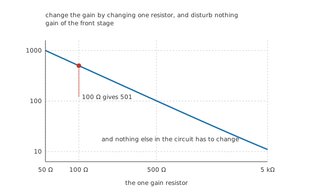
One resistor, and nothing else in the circuit has to move when it does.
There is a second benefit hiding in that arrangement. The gain lives in one resistor, so changing it disturbs no matching anywhere. In a plain difference amplifier the gain and the matching are the same four resistors, so every gain change is a rematching job.
Engineer
How much rejection the measurement actually needs
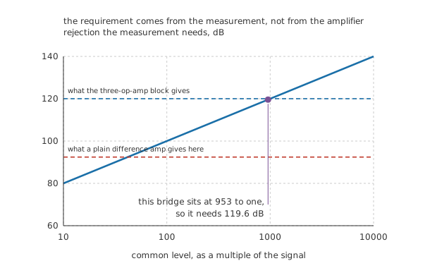
The requirement comes from the bridge. The two dashed rules are what the circuits can do.
Rejection figures on datasheets are meaningless until you know what the measurement asks for, and the measurement asks for something specific.
Worked example — Working out the requirement
The common level is 2.0 V and the signal is -2.098 mV, so the common level is 953 times the signal.
For the common-mode error to stay below 0.10 % of the signal, the rejection has to be that ratio divided by that fraction.
Which is 119.6 dB, and it came entirely from the bridge. No amplifier was mentioned.
Worked example — What the three-op-amp block delivers
Make one of the four difference-stage resistors 10.01 kΩ, which is 0.10 % high. Its common-mode gain becomes 0.000500.
The front stage amplifies the difference by 501 and passes the common level at unity, so the whole circuit's rejection is 120.0 dB.
That clears the requirement by 0.44 dB, which is not much of a margin and is the right amount to know about.
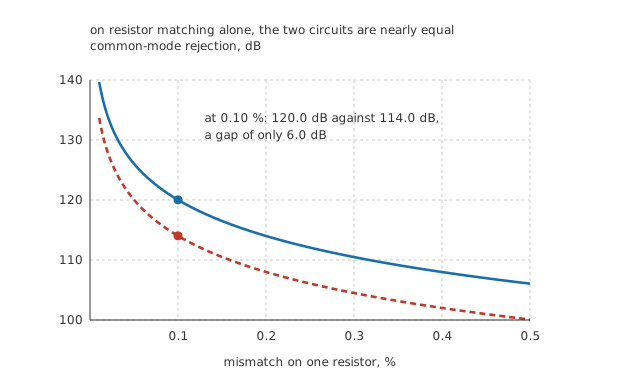
Two traces that stay close together. This figure is here to rule something out.
Now the awkward part, and it is worth being honest about it. Compare that with a plain difference amplifier built for the same total gain of 501, using 10 kΩ and 5.01 MΩ, with the same 0.10 % on one resistor. Its common-mode gain is 0.000997, so it manages 114.0 dB.
That is only 6.0 dB worse. On resistor matching alone the two circuits are nearly equal, and any explanation of instrumentation amplifiers that stops at "better matching" has not explained anything.
Professional
And then you connect the gauge
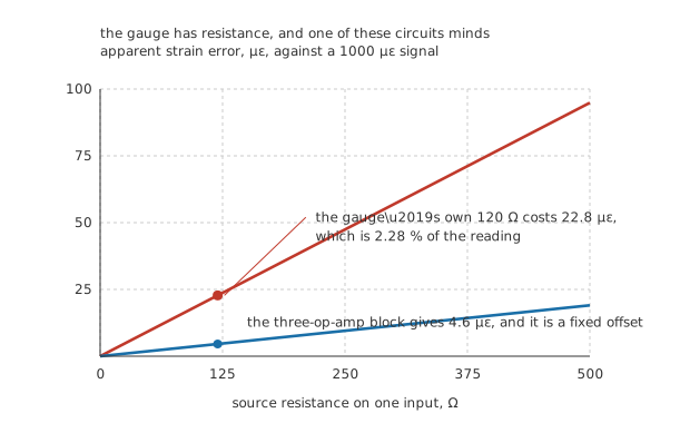
Both traces start at zero with no source resistance. Only one of them stays there.
The gauge is not a voltage source. It is 120 Ω of metal, and the bridge arms around it are the same, so anything connected to that bridge is fed through real resistance.
For the plain difference amplifier that resistance is in series with one of its input resistors, which means it is part of the matched network and it is not matched to anything.
Worked example — What the gauge's own resistance costs
Put 120 Ω in front of one input of the plain circuit, with all four of its resistors exact. That half's gain falls to 495 while the other half's does not, so the common-mode gain becomes 0.01183.
Rejection collapses to 92.4 dB, which is 27.2 dB short of what the measurement needs.
Referred back to the input that is 47.8 µV of error, which reads as 22.8 µε of strain that is not there: 2.28 % of the reading.
The instrumentation amplifier's rejection does not change at all, because its inputs are amplifier terminals and the source resistance has nothing to unbalance.
Worked example — What replaces the error
The front amplifiers draw 80 nA of bias current, and that current through 120 Ω produces 9.6 µV.
As strain that is 4.6 µε, which is not nothing.
But it is a fixed offset that does not track the excitation, so it reads the same with the gauge unstrained and can be zeroed once. A common-mode error cannot, because it moves with everything.
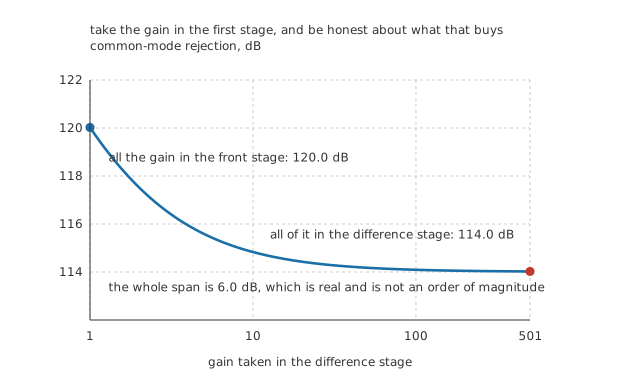
The whole span is six decibels. The rule is real and it is not an order of magnitude.
Take the gain in the first stage, and know what that buys
There is a piece of advice attached to this circuit that everybody repeats: put the gain in the front stage, not the back one. It is correct, and it is worth measuring rather than repeating.
Split the same total gain of 501 differently and the rejection moves between 120.0 dB and 114.0 dB. That is 6.0 dB, and most of it is lost within the first decade of gain moved. So the rule is worth following and it is worth about six decibels, which is a great deal less than the difference between the circuits and rather less than the way it is usually told.
The real difference is the inputs, and it is the only one that matters here. Everything else is detail.
Choosing one
Use a difference amplifier when the sources are stiff — an op-amp output, a low-impedance divider, anything whose resistance you know and can match.
Use an instrumentation amplifier when they are not — sensors, bridges, anything on a cable, anything whose source resistance changes with what it is measuring.
Work out the required rejection first. It comes from the ratio of common level to signal and the error you will accept, and it is a property of the measurement rather than of any amplifier.
And remember what it does not fix. Bias current, offset, drift and noise all still arrive, and on a millivolt signal they arrive loudly. Real op-amp limitations is the next lesson but one, and it is where a measurement circuit's remaining errors live.
Common mistakes
- Explaining an instrumentation amplifier by its resistor matching — at the same gain and the same 0.10 % mismatch the two circuits give 120.0 dB and 114.0 dB, a gap of 6.0 dB. The matching is not the point.
- Forgetting the source is part of a difference amplifier's network — the gauge's own 120 Ω drops the plain circuit from 120.0 dB to 92.4 dB, which is 27.2 dB short of the 119.6 dB this measurement needs.
- Quoting a rejection figure without a requirement — this bridge's common level is 953 times its signal, so holding the common-mode error to 0.10 % of the reading needs 119.6 dB. A different bridge needs a different number.
- Assuming the instrumentation amplifier fixes everything at the input — it removes the common-mode error and replaces it with a bias-current offset: 80 nA through 120 Ω is 9.6 µV, or 4.6 µε. That one is fixed and can be zeroed, which is the difference that matters.
- Changing the gain by changing the difference stage — the gain belongs in the one 100 Ω resistor, where changing it disturbs no matching. Changing the difference stage's resistors is a rematching job every time.
- Treating the front stage's gain as free — moving all 501 of it into the difference stage costs 6.0 dB of rejection, and moving even a factor of ten costs most of that.
Frequently asked questions
Why are there three op-amps rather than two?
Because the front pair does two jobs at once: it buffers each input, and it produces the differential gain across the single gain resistor. A two-op-amp version exists, is cheaper, and gives up the symmetry, which shows up as a common-mode rejection that varies with frequency and a common-mode range that is not the same for both inputs. The three-op-amp arrangement is what you get when you want the symmetry.
How can one resistor set the gain of two amplifiers?
Because both inverting terminals follow their own non-inverting inputs, so the whole input difference appears across that resistor and nothing else. The current it drives has to flow through both feedback resistors, so the difference between the two outputs is the input difference multiplied by one plus twice the feedback resistor over the gain resistor.
Does the front stage do anything about the common-mode signal?
No, and that is deliberate. It passes the common level at a gain of one while amplifying the difference by 501, so the ratio of the two improves by 501 before the difference stage ever sees them. The difference stage then only has to reject what is left.
Can I buy this as one part?
Yes, and for anything precise you should. An integrated instrumentation amplifier has the four difference-stage resistors trimmed on the die, which gets the matching far beyond what discrete resistors reach, and it brings the gain resistor out to two pins so you set the gain from outside. What it does not have is a way to fix a bad connection to the sensor, which is where most real errors come from.
What limits the common-mode range?
The front amplifiers' own inputs, which have to stay inside their supply-referred range, and their outputs, which have to swing to the common level plus half the amplified difference. On a bridge sitting at half the excitation that is usually comfortable. On a sensor sitting near a rail it often is not, and it is the first thing to check when a circuit works on the bench and not in place.