
Quick Answer
The Wheatstone bridge is two voltage dividers driven from one supply, with a detector connected between their two taps. When both dividers hold the same ratio the detector reads zero, and that balance gives an unknown arm from the other three. Away from balance the reading is the difference between the two taps.
Intuition
Two dividers compared against each other
A voltage divider hands back a fixed fraction of whatever supply drives it. Set two dividers side by side across one supply and there are two fractions to compare. A meter connected between the two taps reads whatever difference those fractions leave. That arrangement is a Wheatstone bridge, complete as it stands: four resistances, one supply, and a detector across the middle.
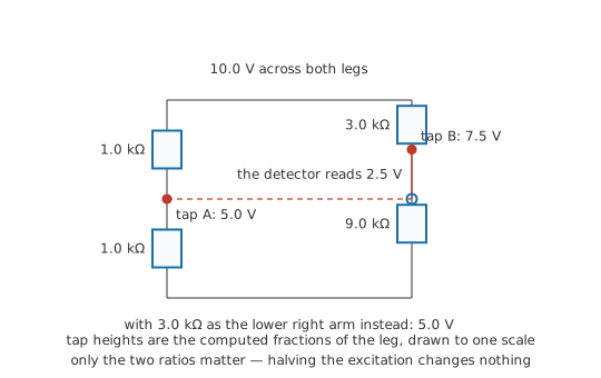
Take a 10.0 V supply. The left divider is 1.0 kΩ above 1.0 kΩ, so its tap sits at 5.0 V. The right divider — 3.0 kΩ above 9.0 kΩ — leaves its tap at 7.5 V. Between them the meter reads 2.5 V.
Now change the right divider's lower arm to 3.0 kΩ. Its tap moves to 5.0 V and the meter falls to 0.0 V. The two legs are still built from different resistances and still carry different currents. They now share a ratio, and that ratio is the only thing the meter responds to.
The supply matters less than it looks. Drop it to 5.0 V and both taps move down to 2.5 V, while the meter goes on reading 0.0 V. Balance is a statement about four resistances: the supply sets where the taps sit, and the arms alone settle whether they agree.
Practitioner
Balancing the bridge to read an unknown arm
Label the four arms by leg: one carries R₁ above R₂, the other R₃ above Rₓ, and the detector bridges the two junctions. The name comes from that bridging, one divider laid across the other. Each junction is a divider output:
The detector reads zero when the two dividers hand back the same fraction, and that happens when R₁ stands to R₂ as R₃ stands to Rₓ. Solved for the arm you do not know:
R₁ and R₂ are the ratio arms: fixed, matched to each other, and usually chosen as a decade ratio so the multiplier is a shift of the decimal point. R₃ is the standard — a decade resistance box, a precision divider, or a calibrated potentiometer — and it is the element you adjust. Adjusting it is how the measurement gets made: turn R₃ until the detector settles on zero, then read the unknown off the standard and the ratio.
Worked example — An unknown arm found by nulling
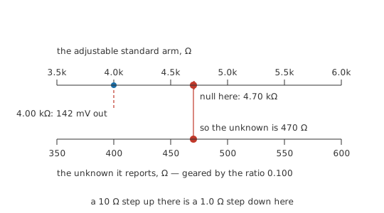
The ratio arms are 1.00 kΩ above 100 Ω, a multiplier of 0.100 on whatever the standard is set to. The bridge runs on 10.0 V.
Start with the standard at 4.00 kΩ. The detector reads 142 mV, positive, so the right-hand tap is sitting above the left and the standard is too small. Raising it to 4.70 kΩ brings the detector to 0.0 mV, and the unknown arm is then the standard times the ratio: 470 Ω.
The ratio scales the resolution along with the value. A smallest step of 10 Ω on the standard arrives at the answer as 1.0 Ω, so a box good for three digits reports the unknown to three digits too.
That answer was assembled out of resistances alone. Excitation, detector gain, detector input resistance and detector calibration all stayed outside it, because at balance no current crosses the detector and the one thing asked of it is to tell zero from not-zero. The answer rests instead on the accuracy of the three known arms, which is why bridge resistors are the expensive kind — close-tolerance parts with low temperature coefficients, and a standard whose own calibration can be traced to something better.
Charles Wheatstone gave the circuit its currency and its name; Samuel Hunter Christie had described the same arrangement earlier.
At the bench, protect the detector while the bridge is still far from balance — a resistor in series with it, or a shorting link across a sensitive movement, removed only for the final approach. Choose the excitation for a comfortable null rather than for accuracy: more of it makes the same imbalance easier to see, up to whatever the arms can dissipate.
The bridge resists reduction. Series and parallel steps both need a pair of arms that share their nodes, and this circuit offers no such pair, so network reduction has nowhere to start on it. Questions asked away from balance go instead to nodal analysis, a delta-wye conversion, or the two-divider treatment set out below.
Engineer
The output either side of balance
Setting the two ratios equal
Both taps are divider outputs measured from the same rail, so with the detector drawing nothing the output is one divider result minus the other. Put that difference at zero and the two fractions are equal: R₂ ⁄ (R₁ + R₂) = Rₓ ⁄ (R₃ + Rₓ). Cross-multiply and the R₂ Rₓ term appears on both sides and cancels, leaving R₂ R₃ = R₁ Rₓ.
The excitation dropped out during the cross-multiplication, and that is what became of the halved supply at the start of the lesson.
Away from balance
No compact formula covers the general case, so the route is to evaluate the two dividers and subtract.
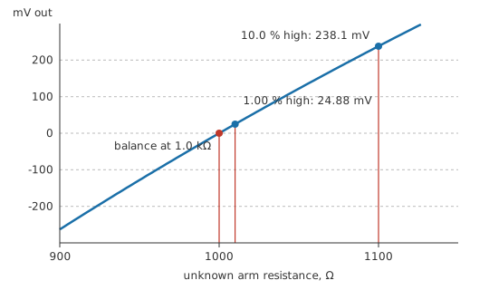
Take four nominally equal arms of 1.0 kΩ on 10.0 V, both taps at 5.0 V, and lift one arm by 1.00 % to 1.010 kΩ. The output moves to 24.88 mV.
A useful approximation sits beside that figure. For a small fractional change in one arm of an equal-armed bridge, the output is close to the excitation times the fraction, quartered — here 25.00 mV, which overstates the true result by 0.50 %. Push the same arm to 10.0 %, or 1.100 kΩ, and the output reaches 238.1 mV where the approximation still predicts 250.0 mV, now 4.76 % high. The characteristic begins as a straight line and then bends away from the approximation, always on the side that overstates.
Nulling and deflecting are different measurements
The choice between them decides what has to be good in the rest of the instrument. Nulling puts the answer in the balance condition, so the three known arms carry it between them. Excitation value, excitation drift, detector gain and detector linearity all leave the calculation. The detector contributes its resolution alone, since the limit on the measurement is the smallest imbalance it can still distinguish from zero.
Deflecting leaves the arms where they are and reads the output. It is quicker, and it can follow a quantity that is still changing, which is what a sensor bridge does all day. Excitation is now inside the answer: output is proportional to it, so a one per cent error in the supply is a one per cent error in the reading. Halve the excitation to 5.0 V and the same imbalance reads 12.44 mV. Detector gain error arrives by the same route, and both have to be calibrated or made stable.
What the detector's own resistance does
With the bridge balanced the detector carries no current, so its resistance cannot move where the null falls; off balance it can. Seen from the two junctions the bridge is a Thévenin source: the open-circuit voltage is the difference computed above, and the source resistance is each leg's pair in parallel, the two added.
For the bridge just used, that comes to 1.0 kΩ. Put a detector of 3.0 kΩ across it and the 24.88 mV open-circuit figure arrives at its terminals as 18.6 mV. A high-impedance amplifier makes that loss too small to matter. A moving-coil movement leaves it large enough to count, and a bridge read that way is calibrated with the movement connected.
Professional
Bridges that measure something physical
Quarter, half and full
A strain gauge is a resistance that changes by a small fraction when the surface it is bonded to stretches. Fractions of that size are awkward to measure against an absolute scale and straightforward to measure as an imbalance, which is what the bridge contributes here: it subtracts a large steady resistance and leaves the change behind.
Worked example — One, two and four active arms
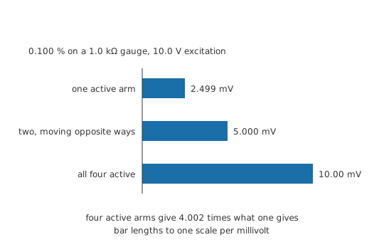
Take four arms of 1.0 kΩ on 10.0 V, with a strain worth 0.100 % in resistance.
One active gauge against three fixed arms makes a quarter bridge, and the output is 2.499 mV.
Put two active gauges in the same leg, one stretching while the other compresses, as on the top and bottom faces of a bending beam, and the output becomes 5.000 mV. That is double the quarter-bridge figure, and because the two arms of that leg move oppositely the result comes out exactly proportional to the strain.
With all four arms active, opposite arms moving together and adjacent arms opposing, the output reaches 10.00 mV, or 4.002 times the quarter-bridge figure. Four times the sensitivity accounts for most of that, and the small excess is the curvature the quarter bridge had already given away.
A dummy gauge in the adjacent arm
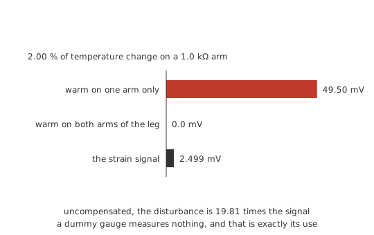
Temperature moves a gauge's resistance as well, by more than the strain does, and the bridge cannot tell the two apart from one arm. Put a second identical gauge in the arm adjacent to the active one — same leg, bonded to an unstrained piece of the same material, held at the same temperature — and the two arms drift together. An equal fractional change in both arms of one leg leaves that leg's ratio untouched, so the output stays at 0.0 mV however far the pair travels.
Leave the dummy out and the same 2.00 % drift in the active gauge alone appears at the output as 49.50 mV — some 19.81 times the strain signal the bridge was fitted to report. Half and full bridges inherit the protection, since their active gauges already sit in pairs. The compensation is only as good as the thermal match, so the dummy belongs on the same specimen and in the same airflow rather than on a nearby bracket.
Three wires to a remote sensor
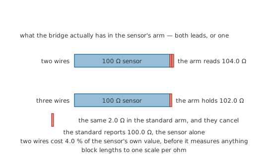
An RTD sits where the temperature is, which is rarely where the bridge is. Run it on two wires and both leads land inside the sensor's arm: a 100 Ω element on 2.0 Ω leads presents 104.0 Ω, an error of 4.0 % before the element has responded to anything, and one that moves with the cable's own temperature.
Three wires split the leads between two arms. One lead brings the sensor's arm to the bridge, a second brings the standard arm to the sensor's other terminal, and the third joins the detector to the junction and carries almost no current. Sensor arm and standard arm each pick up one lead, and with equal ratio arms the balance condition subtracts one from the other, so the standard reports 100.0 Ω, which is the element by itself.
That cancellation depends on the ratio arms being equal, the leads matching in gauge and length, and both leads staying at the same temperature along the run. Four-wire connections sidestep the question by separating the current path from the sense path, and they are the usual choice once the sensor resistance is low enough for contacts to matter.
Excitation: sensitivity against self-heating
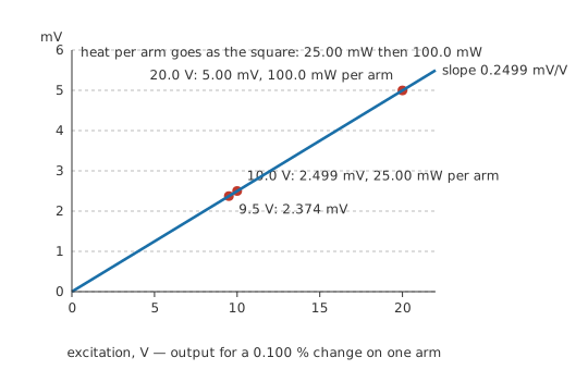
Output is proportional to excitation, so raising the excitation raises the signal, and the heat in the arms grows faster still. Each leg of the worked bridge is 2.0 kΩ across 10.0 V, carrying 5.0 mA, so every arm turns 25.00 mW into heat. Take the excitation to 20.0 V and the same imbalance reads 5.00 mV, double what it was, while the leg current becomes 10.0 mA and each arm is dissipating 100.0 mW.
Where that heat goes decides the ceiling. In a strain gauge it has to leave through the specimen it is glued to; in an RTD it raises the very temperature under measurement. Both therefore carry a limit on measuring current. Pulsed excitation — energise, sample, switch off — raises the signal without raising the average heat, at the cost of settling time on every reading.
Letting the reference cancel itself
Since deflection output is proportional to excitation, bridge sensitivity is quoted per volt of excitation: the quarter bridge above is 0.2499 mV/V. Ratiometric measurement follows from that per-volt figure.
Feed the bridge from the same reference that sets the full-scale range of the converter reading it, and output and full scale move together. Let the reference sag by 5.0 %: excitation falls to 9.5 V, the output falls to 2.374 mV, and sensitivity is still 0.2499 mV/V. Full scale fell in the same proportion, so the converter's code has not moved at all. The reference's absolute accuracy and its long-term drift leave the answer. Its noise stays in, along with anything the excitation path and the measurement path do differently from each other.
Between bridge and converter sits an instrumentation amplifier, since the wanted signal is a few millivolts of difference riding on a common-mode voltage of about half the excitation, and that is the shape of signal it exists to handle.
Common mistakes
- Reading the bridge as four resistors in series and parallel. No two arms share both of their nodes, so neither reduction step applies. Off balance it wants nodal equations, a delta-wye conversion, or the two-divider treatment.
- "The supply drifted, so the reading is wrong." That holds for a deflection reading and fails for a null, and which mode you are in decides whether excitation accuracy belongs in the error budget at all.
- A compensating gauge in the opposite arm. Opposite arms add their changes at the output; adjacent arms in the same leg subtract. An element fitted diagonally doubles the drift it was meant to remove.
- Trusting the quartered approximation far from balance. It is good to a fraction of a per cent at one per cent imbalance and several per cent at ten, and it always errs on the generous side. Evaluate the dividers when the excursion is large.
- A detector whose resistance is comparable with the bridge's own. It costs nothing at a null and divides the output down in deflection. Compare it against the two legs' parallel pairs added together before trusting a calibration.
- Sizing the excitation on signal alone. Arm dissipation follows its square, and in a sensor bridge the heat lands inside the thing being measured.
Frequently asked questions
Why is a bridge more accurate than measuring the resistance directly?
A null measurement replaces an absolute reading with a comparison. The answer is built from three known resistances and a ratio, so the accuracy it inherits is theirs, and the supply's and the meter's stay outside the answer. A direct reading, by contrast, is only as good as the instrument's own calibration at that point on its scale.
Does the bridge need a stable, accurate supply?
For nulling, no: the excitation cancels out of the balance condition, and its only job is to make the imbalance visible to the detector. For deflection it matters directly, since the output is proportional to it. That is why sensor bridges either use a precision reference or arrange for that reference to cancel ratiometrically at the converter.
What does the sign of the output tell me?
The sign tells you which leg is holding the higher fraction of the supply. Working towards a null, it says which way to turn the standard, and it reverses as you pass through balance, so a detector that has changed sign has been taken past the null rather than towards it.
Can a Wheatstone bridge measure very low or very high resistances?
It can at both ends, within limits. Low values are swamped by lead and contact resistance in the arms, which is what the Kelvin double bridge, with its extra pair of ratio arms, was designed around. High values run into leakage across the board and insulation, and into a detector that has to resolve a very small imbalance from a very small excitation current.
Why fit four active gauges when one would already work?
Sensitivity, linearity and rejection all improve together. Four arms give four times the output of one; arranging them so that adjacent arms oppose makes the output exactly proportional to the strain instead of only nearly so; and any influence common to all four — temperature above all — cancels in the ratios rather than showing up as signal.