
Quick Answer
A series-parallel network is a resistor network that can be reduced by repeatedly replacing one series or parallel pair with its equivalent until a single resistance remains. Working outwards again from that equivalent recovers the voltage across and current through every element. Networks such as a bridge cannot be reduced this way.
Intuition
Reducing a network one pair at a time
Few circuits are a single chain or a single set of branches. Most are some of each, and the same two rules still cover them. Series resistances add; a parallel pair combines to something below either one. What a mixed network asks for is an order in which to apply them.
A 60 Ω resistor sits in the wire coming from the supply, and beyond it a 200 Ω and a 50 Ω hang side by side across the same two points. Only the side-by-side pair is unambiguous at this stage — both ends of each land on the same two junctions, which is what parallel means — so the pair goes first, and the two of them together behave as 40 Ω.
Rub out those two and put that single resistance in their place. The drawing is now a plain chain of two resistances, which add to 100 Ω, and a supply of 12 V across that total delivers 120 mA.
One number for the supply is rarely the question, though. The current just found is also the current in the first resistor, since nothing branches before it, so that resistor takes 7.2 V of the supply and the block replacing the pair is left with 4.8 V. Restore the two resistors that block stood for. Both have that same voltage across them, so the 200 Ω carries 24 mA and the 50 Ω carries 96 mA, and between them they come back to 120 mA.
The inward pass reduces a drawing to one number, and the outward pass puts a voltage and a current against every component in it. The total on its own is rarely the figure anyone wanted.
Practitioner
Inwards to one number, then outwards to every branch
On the inward pass, search the network for a pair that is unambiguously one arrangement or the other, replace it with its equivalent, redraw, and search again. Repeat until a single resistance stands between the supply terminals. Qualifying is decided at the junctions:
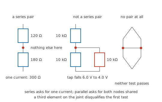
- Two elements are in series if they meet at a junction with nothing else attached to it, so the current through the first has no route except through the second.
- Two elements are in parallel if both of their ends land on the same pair of junctions, so whatever voltage appears across one appears across the other.
An element that passes neither test has to wait while something else is combined first.
Each is written for a fixed number of terms, and each extends without trouble. A series run of any length is a sum over its members, and a parallel group of more than two is taken a pair at a time, with product over sum applied to the running result. Ohm's law then converts between resistances and the quantities the question actually asked for:
The outward pass begins with the single equivalent and the supply voltage, which between them give the supply current, and each reduction is then undone in the reverse of the order it was made. Undo a series step and you are handed a pair carrying the current you already hold, so each member's drop is that current through its own resistance. A parallel step gives back a pair sharing the voltage you already hold, and each member's current follows from its own resistance. Continue until every original component has both numbers against it.
Worked example — Five resistors, in and back out
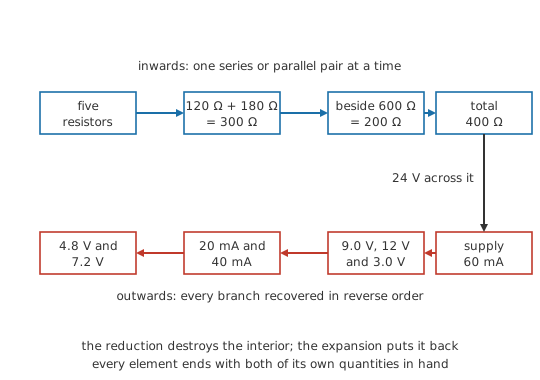
A 24 V supply feeds a network of five. 150 Ω lies in the lead from the positive terminal and 50 Ω in the return lead. Between those two, 600 Ω bridges the pair of inner junctions on its own, and a second path across the same pair of junctions runs through 120 Ω and 180 Ω joined end to end.
R_3 and R_4 qualify first, since the junction between them has nothing else on it. They are in series, and R_34 = 300 Ω. That branch and R_2 now share both of their ends, which makes them a parallel pair, so R_par = 200 Ω. What is left is R_1, R_par and R_5 in one chain, totalling 400 Ω. The supply drives that alone: I = V ⁄ R_total = 60 mA.
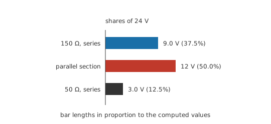
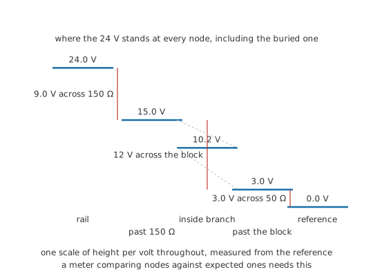
Unwinding starts with the chain, where one current runs through all three members: R_1 takes 9.0 V, R_5 takes 3.0 V, and the block between them holds 12 V. Those three sum to 24 V, which is the supply figure, and a mismatch here would place an arithmetic slip somewhere earlier.
The parallel step comes next, and it stood for two branches at that same voltage. R_2 takes 20 mA and the R_3–R_4 branch takes 40 mA, and those add back to 60 mA.
Last is the series step inside that branch. Both members carry 40 mA, so R_3 drops 4.8 V and R_4 drops 7.2 V.
Every component now has a current and a drop. The 7.2 V across R_4 was never available from the equivalent resistance; it came out of running the reduction backwards, one step at a time.
A ladder network is this method's easiest case, built so that each rung pairs off with the running result and the whole structure collapses from the far end inwards. Kirchhoff's current law and Kirchhoff's voltage law are what license both passes — branch currents add at a node, drops sum round a loop — and where a network defeats reduction those two laws are still available as simultaneous equations, which mesh analysis and nodal analysis systematise.
Engineer
Same current, same pair of nodes
Both tests are statements about connectivity, and neither mentions where a component was drawn. Series means sharing a node that nothing else connects to, and what follows from it is a single current: the shared node has no third branch to carry any of it away. Parallel means sharing both nodes, and what follows there is a single voltage, since a pair of nodes has one potential difference between them and both elements sit across it.
A schematic is a drawing of connectivity, and it can be drawn well or badly. Two resistors printed one above the other, aligned and evenly spaced, look like a series pair whether or not they are one, and two drawn at opposite corners of the sheet are in parallel if their ends land on the same two nodes. What settles it is the copper, whatever the arrangement on the page suggests.
The commonest failure is a node with a third thing on it. Take a divider of 10 kΩ above 10 kΩ across 12 V, tapped at the junction between them. With nothing on the tap the two resistors are in series, they share one current, and the ratio puts the tap at 6.0 V.
Hang a load of 10 kΩ on that tap and the drawing barely changes, but the junction now has three elements on it. The upper and lower resistors carry different currents from that moment, which ends their series relationship. What is in parallel is the lower resistor and the load, which share the tap node and the reference node, and together they come to 5.0 kΩ. Reduce that first and the divider that remains puts the tap at 4.0 V. The 6.0 V predicted by the untouched ratio is a third high, and the voltage divider lesson treats the loaded case in its own right.
Which valid pair goes first never changes the answer. A replacement is an exact statement about what two terminals present to everything outside them, so the network after a step is indistinguishable from the network before it as seen from anywhere else, and any order of valid steps lands on the same equivalent. The order does change how much arithmetic there is on the way, and starting at the point furthest from the supply usually keeps the intermediate numbers simplest.
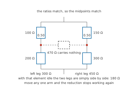
Some networks reduce no further than their original drawing. Wire four resistances as two chains across the supply and bridge the two midpoints with a fifth: 100 Ω above 200 Ω in one chain, 150 Ω above 300 Ω in the other, 470 Ω from midpoint to midpoint. Apply the two tests and nothing passes. Every junction in the network has three elements on it, so no pair meets at a junction of its own, and no two elements share both of their nodes, so no pair is in parallel. The obstacle is the topology rather than any failure to spot the step.
That shape is a Wheatstone bridge, and it is the standard demonstration that this method has a boundary. The tool built for the boundary is the delta-wye transformation, which exchanges a three-terminal triangle of resistances for an equivalent three-terminal star. Perform it on either triangle in the bridge and series and parallel pairs appear where there were none, after which the reduction runs to completion.
One special case escapes without that machinery. Where the two chains divide the supply in the same ratio — 100 Ω to 200 Ω matched by 150 Ω to 300 Ω — the two midpoints sit at the same potential, so the bridging element has no voltage across it and carries nothing. An element carrying nothing can be lifted out without disturbing anything else, leaving two independent chains of 300 Ω and 450 Ω in parallel across the supply, together 180 Ω. Move any one of the four resistances off balance and that escape closes.
Whatever is being combined has to be two-terminal, and its resistance has to be a constant. A lamp, a diode or anything whose value depends on its own current cannot be summed with its neighbours even where the topology permits. A source sitting inside the group is not a resistance either, and it does not combine at all. Reducing a two-terminal network that contains sources is Thévenin's theorem, whose answer is a source together with a resistance instead of a resistance alone.
Professional
What the single number leaves out
An equivalent resistance answers one question: what the rest of the circuit meets at two terminals. Where the heat goes and what a fault looks like on a meter both live inside the box the reduction closed.
Which element runs hottest
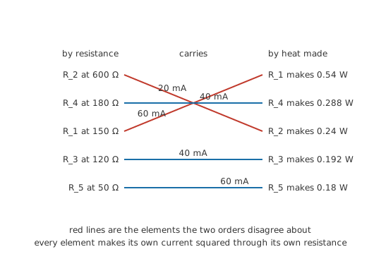
Each element dissipates its own current squared through its own resistance, and the outward pass has already supplied both. Through the five-resistor network above, R_1 takes 0.54 W, R_2 0.24 W, R_3 0.192 W, R_4 0.288 W and R_5 0.18 W, together 1.44 W. That matches what the supply delivers into the equivalent, which was chosen to draw the same current at the same voltage.
Size of resistance is a poor guide to which element runs hottest. R_2 at 600 Ω is the biggest value in the network and lands in the middle of that table, since the parallel split sends two thirds of the current down the other branch. R_1 has a quarter of R_2's resistance and dissipates more than double, because it carries every milliampere the network draws. Dissipation concentrates in the series elements close to the supply in almost any network. A power rating chosen from the equivalent alone therefore says nothing about which of the five needs the larger package, and power dissipation covers the derating that follows.
Tolerance through a reduction
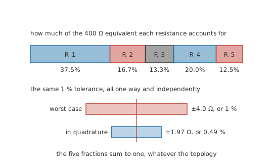
Five 1 % resistors give an equivalent of 400 Ω, and the worst case is a single line of reasoning. Scale every resistance in a network by a common factor and every series sum and every parallel combination scales by that same factor, so the equivalent moves by exactly the component tolerance and by no more than that: 4.0 Ω here, whatever the topology.
Independent deviations do better than that. Each resistance shifts the total in proportion to how much of the equivalent it accounts for, and those five fractions sum to one. A member of a parallel block counts for less than its own value suggests, because the other branch absorbs part of the change. Combined in quadrature rather than added, the five give 0.49 %, or 1.97 Ω, about half the worst case. That figure is honest only where the errors really are independent; one reel at one temperature drifts together and stacks the worst-case way, as resistor tolerance sets out.
Redrawing before the first step
Most networks that look irreducible are drawn badly. A schematic drawn to match a layout puts components where the copper is and leaves the topology to be inferred. Redrawing costs a minute. Give every distinct node one letter, place each element between its two letters, and put the supply terminals at the ends: elements sharing a pair of letters stack as a parallel group, and a letter appearing on exactly two elements marks a series joint. Pairs turn up that the original drawing hid. A network that still shows no pair after that genuinely needs a bridge transform or a set of simultaneous equations, and circuit simulation takes over once the element count passes a dozen or so. Arrays and dividers sold as resistor networks carry their internal topology only in the datasheet drawing.
What the reduction throws away
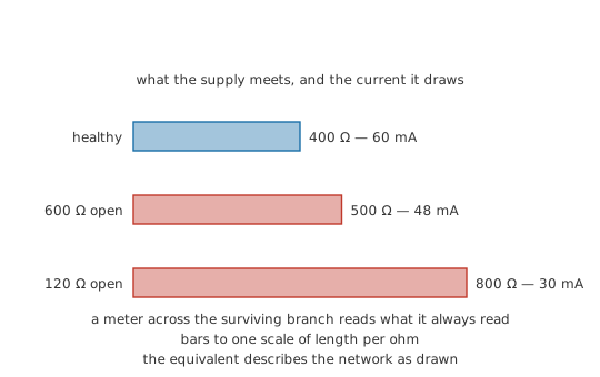
An equivalent keeps no record of what it replaced. Interior node voltages go with the reduction, so a fault-finding session comparing measured node voltages against expected ones works from the outward pass rather than from the total, and which element is dissipating goes the same way. The number also describes the network as drawn: open one resistor in a parallel block and the equivalent moves, while a meter across the surviving branch reads what it always read. Keep the sub-equivalents from each inward step and the outward pass costs a handful of divisions.
Safety
Checking a reduction against an ohmmeter means checking it on an unpowered board. An ohmmeter drives its own small current into the circuit, so a reading taken with the supply connected means nothing and can damage the meter. Remove power, then wait — bulk capacitors hold their charge after the supply is switched off, and a rail can sit near its working voltage for minutes. Confirm zero volts on a voltage range before switching the meter to resistance. In-circuit readings also come back low, since every other path between the probe points is in parallel with the one you meant to measure; measuring V, I and R covers lifting a leg.
Common mistakes
- Two resistors drawn in a line, called a series pair — the test is what else connects to the junction between them, not how neatly they line up. Anything else on that junction means the two carry different currents and cannot be summed.
- Reducing away the element the question was about. An equivalent is a statement about two terminals and keeps nothing about its interior, so note each sub-equivalent as you make it or the network has to be reduced a second time.
- "Product over sum, three at a time." It is the parallel rule written out for exactly two branches. Combine two of them, then put that result through the same formula against the third.
- A load hung on a divider tap. The load and the lower arm share both nodes, which makes them the parallel pair; the two arms of the divider stop being a series pair the moment the tap draws current, and the bare ratio then overstates the tap voltage.
- Grinding at a bridge. Some networks contain no series pair and no parallel pair anywhere in them, and rearranging the drawing will not produce one. Recognise the shape, then transform a triangle into a star or write the loop equations.
- Sizing every resistor in a network from the equivalent's dissipation. The total divides very unevenly between the elements, and the one in the supply lead usually takes the largest share of it.
Frequently asked questions
How do I decide whether two components are in series?
Look at the junction where they meet and count what is attached to it. If those two components are the only things on that junction, the current through one has nowhere to go but through the other, and they are in series. A third connection at that point — a branch, a load, a test point that draws current — ends the series relationship.
Does it matter which pair I combine first?
The answer does not depend on it. Every valid step is an exact substitution, so any order of valid steps reaches the same equivalent. What the order does change is how much arithmetic you do and how ugly the intermediate numbers get; working from the end furthest from the supply towards the terminals usually keeps them tidiest.
What do I do with a network where nothing is in series or in parallel?
Redraw it first, since badly drawn schematics hide pairs that are really there. If nothing appears after redrawing, the network genuinely needs another tool: a delta-wye transformation to convert one triangle of resistances into a star, or mesh or nodal analysis, which solve any linear network without needing reducible topology at all.
I have the equivalent resistance. How do I get one branch current back?
Run the reduction backwards. Divide the supply voltage by the equivalent to get the total current, then undo each step in the reverse of the order you made it, carrying a current forward through series steps and a voltage forward through parallel steps until you reach the branch you want. The equivalent on its own cannot tell you.
Does the same method work for capacitors and inductors?
The topology work is identical — the same two tests identify the same pairs — but the combining rules differ. Inductors follow the resistor rules, adding in series. Capacitors invert them, adding in parallel and combining reciprocally in series, and inductors in series and parallel carries the extra complication of mutual coupling between nearby windings.