
Quick Answer
Inductances in series add, and inductances in parallel combine like parallel resistances, giving a total below the smallest. Those rules hold only while the coils share no magnetic flux. Any coupling between them adds or subtracts a mutual term, and the same two parts can then measure very different totals.
Intuition
Back to the resistor rules
Capacitors reversed the arithmetic everyone had learned for resistors. Inductors put it back. Wire two coils one after the other and their inductances add; wire them side by side and the total falls below the smaller of the two, exactly as parallel resistances do.
The reason is the same one that made resistors behave that way. Inductance opposes a change of current, and putting two coils in a row means the current has to fight past both of them, so the opposition adds. Offering the current two coils side by side gives it two paths to divide between, and any extra path makes the going easier.
There is a condition attached, and it has no equivalent in the resistor world. These rules assume the two coils know nothing about each other magnetically. A resistor cannot influence its neighbour by sitting near it; a coil can, because its magnetic field extends beyond its own winding. If any of one coil's flux passes through the other, the simple arithmetic stops being right, and it can be wrong by a lot.
Whether that matters depends entirely on the geometry. Two surface-mount chokes at opposite corners of a board are effectively independent. Two coils wound on the same core are so strongly coupled that they behave as a single component. Most real cases are somewhere between, and the first job in any inductor network is to decide which of those situations you are in.
Practitioner
The two rules, on parts that do not couple
Both library entries name the uncoupled case explicitly, because that assumption is the thing most likely to be wrong. For two coils in a row:
and for two side by side:
Worked example — One pair of chokes, wired both ways
Take 100 µH and 47 µH, mounted far enough apart that neither sees the other's field.
In a row they come to 147 µH, the straight sum.
Side by side they come to 32.0 µH, below the smaller of the two.
Adding a third of 22 µH in parallel with that result brings the total down again, to 13.0 µH. Each extra path lowers the total, just as it does with resistors.
Working a mixed network follows the resistor discipline unchanged: identify a group that is clearly in series or clearly in parallel, replace it with its equivalent, redraw, repeat. The series-parallel networks lesson sets out the method, and nothing about it changes here except the components.
The general rules extend the same way as well. Any number in series is the plain sum. Any number in parallel is the reciprocal of the sum of the reciprocals, and the two-inductance product-over-sum above is that rule collapsed for exactly two parts — which is why the library entry says two.
Why do it at all? Series connection is the usual way to reach a value no single stocked part offers, and it raises the total current rating no further than the weakest part allows. Parallel connection is done for current rather than for inductance: two coils side by side share the current, so each runs cooler and each stays further from saturation, at the cost of halving the inductance if the parts are equal.
Engineer
Shared current, shared voltage, and what coupling does to both
Both rules fall out of the defining relation, that a coil's voltage is proportional to how fast its current is changing. Put two coils in series and the same current runs through both, so both experience the same rate of change; each produces its own voltage, and KVL adds those voltages along the loop. A single coil producing that same total voltage for that same rate of change would need an inductance equal to the sum, which is the series rule.
Put them side by side instead and the argument inverts. Both now share the voltage, so both see the same rate of change of their own currents, and each contributes a rate of change in inverse proportion to its inductance. The total current's rate of change is the sum of the two, and the single coil equivalent to that pair must have an inductance whose reciprocal is the sum of the reciprocals. Which is the parallel rule, and it is the same reasoning that gives resistors theirs — voltage shared, currents added.
Both arguments assumed one thing without saying so: that each coil's voltage depends on its own current alone. Once two coils share flux that stops being true, the mutual term enters, and the simple rules stop applying. For a series pair wound so their fluxes reinforce:
and reversing either winding makes the mutual term subtract instead. The size of the term comes from the coupling coefficient:
Worked example — Two identical coils, and three different answers
Take two coils of 100 µH each. Mounted apart, in series, they measure 200 µH — the plain sum.
Now bring them together until the coupling coefficient reaches 0.5, giving a mutual inductance of 50 µH.
Wired so their fluxes aid, the pair now measures 300 µH.
Reverse one of them, so the fluxes oppose, and the same two coils measure 100 µH — the inductance of a single coil, from two of them in series.
A three-to-one spread on identical parts, decided entirely by how they are mounted and which way round they are wired. That is the reason the library entries carry "uncoupled" in their names, and it is why a circuit that worked on a prototype can fail on a production layout where the inductors sit closer together.
Parallel coupled inductors follow the same pattern with a messier expression, and the practical consequence is what matters: coupled parallel coils do not simply divide. In a coupled-inductor buck converter that is exploited deliberately, using the coupling to shape the ripple currents; in a badly laid-out board it is a surprise. The mutual inductance lesson covers the measurement that resolves it, since the series-aiding and series-opposing readings give M without needing to know the geometry.
The limits of everything above are worth naming. These are relationships between ideal inductances, and they say nothing about winding resistance, which adds in series and divides in parallel exactly as any resistance would. They say nothing about saturation, which is a per-part limit that no combination rule can average away. And they hold only below the parts' self-resonant frequencies — above those, the winding capacitance dominates and combining "inductances" is meaningless because neither part is one.
Professional
Why parallel inductors rarely share the work
Paralleling inductors to carry more current is a standard move, and it works less well than the arithmetic suggests.
Worked example — Two chokes, one rail, unequal shares
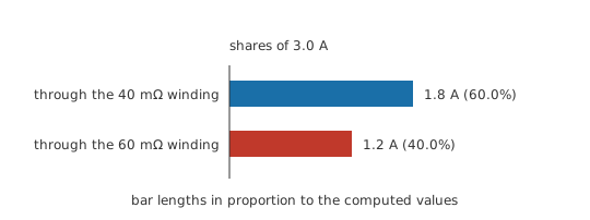
Two nominally identical inductors sit in parallel carrying 3.0 A of DC. Their winding resistances differ a little, at 40 mΩ and 60 mΩ — an ordinary spread within one part number.
At DC it is the resistances, not the inductances, that set the split. The lower-resistance part takes 1.8 A and the other takes 1.2 A.
A twenty per cent spread in winding resistance has produced a fifty per cent difference in current. The part carrying more is closer to saturation and running hotter, which is the opposite of what paralleling was supposed to achieve.
The AC picture divides by inductance instead, so ripple current follows the tolerance on the inductance while DC follows the tolerance on the resistance. Neither is tight on a commodity part, and the two need not favour the same inductor. Designs that must share properly either use a single larger part, or use current-sharing control that measures each branch, or accept the imbalance and derate every branch to the worst case.
Series connection has its own bookkeeping and it is more forgiving. The inductances add, which is what you wanted, and so do the winding resistances, which is the price. The saturation current of the string is that of its weakest member, not an average, and the self-resonant frequency of the pair sits below either part's, because the total inductance is larger while the winding capacitances have not gone away.
Layout is a design parameter in this material rather than a detail. Two inductors on one board couple through the air between them, and the coupling depends on their spacing, their orientation and whether either is a shielded or a drum-core part. Unshielded drum cores throw a substantial external field and couple readily; shielded and toroidal parts keep most of their flux inside and couple far less. Mounting adjacent coils at right angles, or putting a shielded part between two unshielded ones, is a cheaper fix than redesigning the magnetics.
Where a value must be trimmed rather than switched, series connection is usually the answer, since the sum is exact and a small coil in series with a large one adds predictably. Parallel trimming is a poor tool: the total is dominated by the smallest inductance, so a large part in parallel with a small one barely moves it, and the arrangement doubles the number of things that can saturate.
Cost and board area usually settle it. One part with the right rating beats two that share badly, and the times paralleling genuinely wins are when no single part exists at the required current, when height is constrained, or when spreading the heat over two footprints solves a thermal problem that a single part could not.
Common mistakes
- Applying the uncoupled rules to coils that share flux — the mutual term can move the total by a factor of three on identical parts, and its sign depends on which way each is wound.
- Assuming parallel inductors share current equally — the DC split follows winding resistance and the AC split follows inductance, and ordinary part tolerance makes both uneven.
- Treating the saturation rating of a series string as an average — the string saturates when its weakest member does.
- Combining inductances above their self-resonant frequencies — above resonance the parts are capacitive, and there is no inductance left to combine.
- Using a parallel inductor to trim a value — the total sits near the smaller part, so a large one in parallel changes almost nothing while adding another thing that can saturate.
- Ignoring the layout — two unshielded drum cores placed close together are a coupled pair whether or not the schematic says so.
Frequently asked questions
Do inductors in series add?
Yes, provided they share no magnetic flux. Series inductances add and parallel inductances combine like parallel resistances, which is the opposite of the way capacitors behave.
Why do the rules say 'uncoupled'?
Because any flux shared between the two coils adds a mutual term that the simple rules leave out. Depending on the winding sense that term either adds to or subtracts from the total, and it can be large.
Can I parallel two inductors to carry more current?
Only with care. The DC current divides according to winding resistance rather than inductance, so ordinary tolerance leaves one part carrying noticeably more — closer to saturation and running hotter than the other.
What happens to the saturation rating when inductors are combined?
In series, the string saturates when its weakest part does; the ratings do not add. In parallel, each part sees its own share of the current, so the branch carrying the most is the one that saturates first.
How do I stop two inductors on one board coupling?
Increase the spacing, mount them with their axes at right angles, or choose shielded or toroidal parts that keep their flux inside. Unshielded drum cores are the ones that couple most readily.