
Quick Answer
Kirchhoff's voltage law states that the voltages around any closed loop of a circuit sum to zero, once each element is given a sign by the direction you travel round the loop. Rises and falls cancel because the walk ends at the point it started from, and one point holds one potential.
Intuition
Coming back to where you started
A point in a circuit holds one potential. Ask what the potential is at a particular junction and there is a single answer to be had. A loop is a route that leaves some point and eventually arrives back at it, so whatever the route did to the potential along the way, the arrival has to agree with the departure.
Put a meter on that. A cell of 6.0 V drives three elements joined in a ring, and the black lead stays clipped to the cell's negative terminal while the red lead walks round. Cross the cell and the red lead reads 6.0 V. Past the first element, which drops 1.5 V, it reads 4.5 V. Past the second, dropping 3.0 V, it reads 1.5 V. The third drops 1.5 V and the red lead is back on the terminal it set out from, reading 0.0 V.
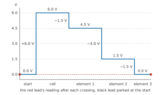
The three elements could have been anything. A resistor, a lamp and a length of thin wire would have closed on the same final reading, since that reading is taken at the point the walk began. The individual rises and falls are free to be any size at all, provided they cancel.
The same cancellation, used in reverse, supplies a number nobody measured. With a known supply and three elements in one loop, any one of the four figures follows from the other three. A part buried under a heatsink, or too hot to touch, or with no resistance anybody could look up, still gets a drop written next to it on the drawing. Kirchhoff's current law makes the matching statement at a junction, where the quantity that cannot be created or lost is charge instead of energy.
Practitioner
Putting a loop equation on paper
Begin by choosing a direction to travel. The answer comes out the same clockwise or anticlockwise, provided the choice holds good for the whole of the loop. Then go round in that direction, writing one term per element as you cross it, and set the total to zero.
Each sign comes from which terminal of the element you meet first. Enter at the minus terminal and leave at the plus and the potential rose, so the term is positive; enter at the plus and leave at the minus and it fell, so the term is negative. The same operation covers sources. A battery crossed from minus to plus contributes a rise, and the same battery crossed the other way contributes a fall, which is what a cell does when something larger is charging it.
A resistor's polarity marks follow from the direction you assumed its current takes, and a guess that turns out backwards can be left standing. That element's term simply comes out negative, which reads as a drop of that size with the current in the branch running against the arrow, and it is a complete answer. Sign errors arrive later, when arrows get redrawn halfway through a solution.
A loop may hold three elements or thirty, and an expression has a fixed number of terms, so no formula states the law in general. The words do that — the voltages around a closed loop sum to zero — and what a formula library can offer is one loop at a time. Here it offers a source and three elements in a single loop:
Most of those drops arrive from the current in the loop and the element's own resistance:
Worked example — A lamp with no resistance you could look up
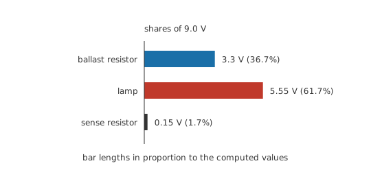
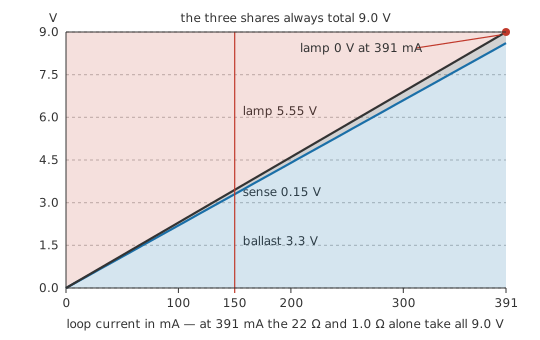
A 9.0 V bench supply feeds one loop: a ballast resistor of 22 Ω, a small filament lamp, and a sense resistor of 1.0 Ω whose job is to report the current. All three carry the same current, and the sense resistor puts it at 0.15 A.
That current settles two of the three drops. V_ballast = I × R_ballast = 3.3 V, and the same product across the sense resistor is 0.15 V. The lamp offers no resistance to multiply by, so a meter goes across it and reports 5.55 V.
Now close the loop. The three drops together come to 9.0 V, the supply figure, so every volt the supply produced has been located and no fourth drop is hiding in the wiring or in a connector.
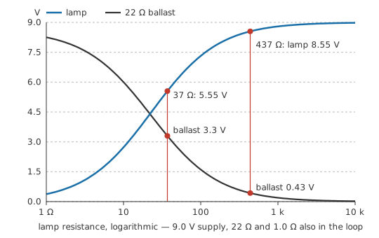
Reading that last drop off a meter and deducing it from the loop equation come to the same thing, and either route reaches what no marking on the lamp reports — its resistance while lit, R = V ⁄ I = 37 Ω. The same filament measured cold and unpowered reads far lower, so the figure describes this operating point and not the part.
A single-loop series chain is the easy case, with every element crossed the same way and no bookkeeping to get wrong. The discipline of a fixed traversal direction begins to tell once two loops share a branch, and writing the equation once for each of a chosen set of loops is mesh analysis. Applied to two resistors in one loop the law gives the proportional result behind the voltage divider. On a bench it is the reasoning behind every expected node voltage a fault-finding session compares its readings against.
Engineer
A coulomb taken once round the loop
The volt is defined as energy per unit charge: one joule of work per coulomb moved between two points means a potential difference of one volt between them, as voltage sets out. That definition turns a loop equation into an energy statement wearing different units.
Carry one coulomb once round a loop. At each source it gains energy; at each resistance it gives energy up as heat. Bring it back to the point it left and it is where it started, in the state it started in, holding the energy it started with — so what it gained and what it gave up were equal. Divide the whole audit by the size of the charge and every term becomes joules per coulomb, which is volts, and the audit reads as the law.
The argument rests on a property of the field: the energy of a charge depends on where the charge is and not on how it got there. A field with that property is called conservative, and it is the property that permits a single number, a potential, to be attached to each point in the circuit. Grant that and the law is not so much derived as restated. Crossing an element from node a to node b contributes the potential at a minus the potential at b. Go all the way round and every node's potential has appeared exactly twice, once positive and once negative, so the sum collapses to zero for any loop in any circuit. The zero comes out of the bookkeeping on potentials, before any element in the loop has been named.
Traversal direction drops out of that immediately. Reverse the direction and every term changes sign, which multiplies the whole equation by minus one and constrains what it constrained before. Walk a loop in the opposite sense from a colleague and the two of you write down the same equation.
Worked example — The same equation multiplied by the loop current
A supply of 5.0 V charges a cell sitting at 3.6 V through a series resistance of 2.8 Ω. Travel the loop the way the supply drives: a rise at the supply, a fall across the resistance, a fall across the cell, back to the start.
Both sources are fixed, so the resistance is left with the difference, 1.4 V. Its current follows from that drop, I = V ⁄ R = 0.5 A, and one loop means that current is also the supply's and the cell's.
Multiply every term of the loop equation by that current. Volts become watts and the equation becomes an account per second: the supply delivers 2.5 W, the resistance turns 0.7 W into heat, the cell takes 1.8 W and stores it. Zero multiplied by a current is still zero, so the account balances by construction.
The cell is the term to watch here, since the loop crosses it from plus to minus. It is a source in the loop and a load in the account at the same time, and the equation treats it exactly as it treats the resistance, apart from the fact that its share of the power can be got back out later.
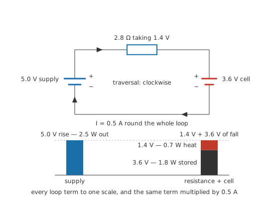
That power balance is the loop equation with each term multiplied by the one quantity common to every element in a single loop, rather than a second law standing beside it. Energy conservation and the voltage law resist being separated because one of them simply is the other scaled by current.
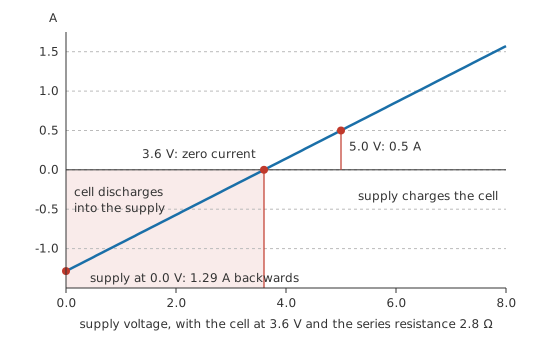
The argument leaned on conditions it never stated. It assumes the circuit is lumped — that its physical size is small compared with the wavelength of anything happening in it, so that a wire is a connection and not a structure with its own behaviour along its length. It assumes as well that no changing magnetic field threads the loop being walked. The magnetic condition is the one that fails on real benches, and the way it fails turns out to be more useful than the inconvenience it causes.
Professional
When the loop encloses a changing magnetic field
Faraday's law gives the electric field a second source. Besides charges, a magnetic field changing in time drives it, and taken once round a closed path the field then totals the rate at which magnetic flux through that path is changing, with a sign opposing the change, rather than totalling zero. Electromagnetic induction develops the law and magnetic flux defines the quantity being counted.
What gives way is the idea underneath the arithmetic. Where the sum round a closed path is not zero, no single number can be attached to a point as its potential, and "the voltage between these two points" stops being a property of the two points and becomes a property of the route taken between them. Two instruments connected to the same pair of nodes by differently shaped leads then read differently, and both instruments are telling the truth about their own loop.
The probe's loop is part of the circuit
An oscilloscope probe's tip lead and its ground lead enclose an area, and the loop the instrument measures is that area closed through the circuit under test. Flux changing anywhere through it adds a term to the reading, and that term belongs to the probe and not to the node. A ground lead left long and looping encloses a large area beside a switching node throwing flux in every direction; the same probe with a short ground spring against the return pad encloses very little, and its trace is the cleaner one. Scope probe technique fusses about ground-lead length on this account, and two scopes on the same two nodes can be made to disagree by nothing more than how their leads were dressed.
Loop area is a design variable
Read as a design question rather than a measurement one, the same geometry becomes a layout rule. A current and its return enclose an area, that area sets how much flux the pair throws into everything around them, and it equally sets how much flux from elsewhere the pair collects. Bringing the return directly beneath the outgoing path, or providing a plane for it to choose its own shortest route, shrinks the area and reduces emission and susceptibility together. EMI and EMC basics treats the consequences, and ground loops treats the case where the enclosed area was created by wiring one reference to another at two points.
Putting the flux back in the drawing
Representing the coupling as a component rescues lumped analysis. An inductor is this effect deliberately confined to one place: its terminal voltage is the flux term for its own winding, and once that term is a component with two terminals and a defined voltage, the loop equation applies again to the circuit containing it. Flux shared between two separate loops becomes mutual inductance, also a component with terminals. The condition for the rescue is strict: every path by which flux links a mesh must appear in the drawing as an element. Flux threading a loop with nothing on the schematic to represent it is a source the equation does not contain, and no amount of care with signs will find it.
At DC none of this bites and the law is exact within the lumped model. What still catches people there is the assumption that a reference symbol repeated across a schematic marks one node. Return copper has resistance, so two points both drawn as the reference sit at different potentials while current runs between them. That difference is an ordinary resistive drop and a term in somebody's loop equation, and the law is satisfied the whole way round.
Safety
The probe geometry above answers a measurement question. It carries no licence to put a probe on a live converter. A scope's ground clip is connected to the mains earth on any non-isolated instrument, so clipping it to a node that is not at earth potential puts a short across whatever sits between them, with the fault current that implies. Reach for a differential probe, an isolated input, or an isolation transformer before probing anything that is not referenced to earth, and observe the practices in electrical safety fundamentals.
Common mistakes
- Changing traversal direction partway round a loop. The signs of the terms only mean anything relative to one chosen direction, and swapping halfway makes some terms belong to one convention and some to the other. Choose a direction, mark it on the drawing, and finish the loop.
- "The supply voltage appears across every component" — it appears across all of them together, apportioned. A part with the full supply across it in a series loop is usually a part that has gone open, leaving nothing for the others.
- Sources treated as a special category of term. Crossing a source is the same operation as crossing a resistor: note which terminal you met first and take the sign from that. Nothing else about a source enters the loop equation.
- Leaving the wiring, the switch contacts and the connector out of the loop. They are elements in it and they take their share, invisible at signal currents and dominant at high current in thin conductors.
- Correcting a negative result by flipping the assumed current arrow and starting again. The minus sign was the answer to the question of direction, and re-solving only creates fresh opportunities to lose it.
- A loop drawn on the schematic that is not a loop the current can take. The path has to be closed through actual conductors and components. A route that jumps between two points joined by nothing is not a loop and its equation constrains nothing.
Frequently asked questions
Which way round the loop should I go?
Either way. Reversing the direction multiplies every term in the equation by minus one, which leaves the same relationship between the same quantities. You do need to hold one direction for the whole of one loop, and to mark it on the drawing so the signs can be checked later.
Does the law apply to a loop containing capacitors and inductors?
Yes, applied at each instant to the instantaneous voltages. The capacitor's term is whatever its plates hold at that moment and the inductor's term is set by how fast its current is changing, so the terms move with time, but at any one instant they still sum to zero around the loop.
Two of my terms came out negative. Is the solution wrong?
No. A negative term means that element was crossed from its higher-potential terminal to its lower one, or that the current in it runs opposite to the arrow you drew. Both are complete answers. Leave the arrows where they are and read the signs.
Does Kirchhoff's voltage law ever fail?
It holds exactly for the electrostatic case, which covers DC and any circuit small compared with the wavelengths in it. Where a changing magnetic field threads the loop, the sum around that loop equals the rate of change of the flux instead of zero, and "the voltage between two points" then depends on the path taken between them.
How do I handle a loop with more than one source?
Exactly as you handle one with a single source. Each source contributes a term whose sign comes from which of its terminals you meet first on your way round, so sources that oppose each other end up with opposite signs and partly cancel. A charging circuit is the standard case: the charger's term and the cell's term subtract, and the difference is what the series resistance takes.