
Quick Answer
Mutual inductance is the property by which a changing current in one winding induces a voltage in another that shares its magnetic field. Its symbol is M and it is measured in henries, like self-inductance. The coupling coefficient states what fraction of one winding's flux reaches the other.
Intuition
How much of the beam lands on the target
Shine a torch at a small object across a room and only part of the beam actually falls on it. Bring the object closer, or narrow the beam, and the fraction that lands goes up. Move it aside and the fraction drops away, even though the torch is putting out exactly as much light as before.
Two coils behave that way with magnetic field. A coil carrying a current produces a field around itself, and if a second coil sits in that field, some of the field passes through it. How much depends on how close the two are, how they are oriented, and whether anything guides the field from one to the other. When the current in the first coil changes, the field changes, and a changing field through the second coil produces a voltage in it — the same effect that gives a single coil its inductance, except that the cause is now in a different piece of wire.
That is mutual inductance, written M and measured in henries. It says how many volts appear across the second winding for a given rate of current change in the first. No wire runs between them. Nothing conducts. The two are joined only by a magnetic field, and one can be at a completely different voltage from the other.
Everything that depends on this idea depends on that last sentence. A transformer moves power across a barrier that carries no current. A wireless charger moves power across an air gap. And, unhelpfully, a switching supply moves noise into an adjacent signal loop by exactly the same mechanism, which is why coupling is something to design out as often as in.
Practitioner
The coupling coefficient, and the voltage it delivers
Mutual inductance depends on both windings and on how well they share their field. That last part is captured by a single number between zero and one, the coupling coefficient k:
At k = 1 every line of flux from one winding passes through the other, which is the ideal case and is never quite reached. At k = 0 the two ignore each other entirely. Loosely coupled air-cored coils sit at a few tenths; windings sharing a closed ferrite core reach well above 0.99.
Worked example — Two windings on one former
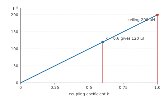
Take windings of 100 µH and 400 µH with a coupling coefficient of 0.6. Their mutual inductance is 120 µH.
Improve the geometry until the coupling is perfect, at 1.0, and M rises to 200 µH — the largest value those two windings could ever show. M cannot exceed the geometric mean of the two self-inductances, because k cannot exceed one.
The working relation is the same shape as the one for a single coil, with M in place of L:
Worked example — What the second winding sees
Change the current in the first winding by 0.5 A over 20 µs. Across the second winding, 3.0 V appears.
The second winding need not be connected to anything for that voltage to exist. It appears across an open circuit just as readily, which is what makes an unterminated winding on a live transformer worth respecting.
Mutual inductance is symmetric, which is not obvious and is genuinely useful: the M that couples winding one into winding two is the same M that couples two into one. A single number describes the pair, whichever way the energy happens to be flowing.
Orientation matters as much as proximity. Two coils on the same axis couple strongly; the same two turned at right angles couple hardly at all, because the field from one runs parallel to the turns of the other and passes through almost none of them. That is a layout tool rather than a curiosity, and it is why the inductors in adjacent switching converters on one board are often deliberately mounted at ninety degrees to each other.
Engineer
Measuring M without knowing k
Series-connecting two coupled windings gives a total inductance that depends on which way round they are wired, because the mutual term either adds to or subtracts from the self terms. Wired so their fluxes reinforce:
Reverse either winding and the flux from one now opposes the flux from the other, so the mutual term changes sign and the same pair measures a good deal less. That gives a measurement route that needs no knowledge of the geometry at all — take both readings and the difference is four times M.
Worked example — Two readings on an LCR meter
The same two windings, series-connected so their fluxes aid, measure 740 µH.
Reverse one of them and the mutual term subtracts instead, giving 260 µH.
The difference between the readings is four times the mutual inductance, so M comes out at 120 µH — the same figure Layer 2 obtained from k, arrived at without measuring anything magnetic.
That is the standard bench method, and an LCR meter with a soldering iron beside it is all the apparatus it needs. It also gives k, since k is M divided by the geometric mean of the two self-inductances, both of which the same meter reads directly.
The dot convention exists to record which way round is which. Two windings on a schematic carry a dot at one end of each, and the convention is that current entering both dotted ends produces flux that aids. Without those dots a coupled pair is ambiguous, and the ambiguity is not academic — the sign of M decides whether a flyback converter's output is positive or negative, and whether a feedback winding stabilises an oscillator or stops it dead.
The energy stored in a coupled pair is not simply the sum of what each winding stores alone. A cross term appears, proportional to M and to the product of the two currents, and it is positive or negative depending on the winding sense. It is that term that lets a transformer take energy in at one winding and deliver it out of another, and its presence is why the two windings cannot be treated as independent components that happen to be nearby.
The model has honest limits. A single k treats the coupling as one number, whereas real windings couple differently at different frequencies as skin effect and capacitance change the current distribution. It also assumes a linear core: once the core saturates, both self-inductances collapse and M with them. And it says nothing about the capacitance between the windings, which provides a second, entirely electrostatic coupling path — the one that carries common-mode noise straight through a transformer that was fitted to block it.
Professional
Leakage, and what the missing flux costs
The flux that fails to link both windings is called leakage, and in a power design it is usually the dominant nuisance.
Worked example — How much flux misses
At a coupling coefficient of 0.6, the fraction of the primary's inductance that does not couple is 64 %. On a 100 µH primary that is 64 µH of leakage inductance, in series with the useful part and coupling to nothing.
Wind the same pair properly, interleaving the layers to reach 0.98, and the leakage falls to 3.96 µH.
Leakage inductance behaves as an ordinary inductor in series with each winding, and it does everything an ordinary inductor does. It stores energy that has nowhere to go when a switch opens, producing the voltage spike that destroys switching transistors in flyback converters. It limits how fast current can transfer between windings, which shows up as a droop on the output of a pulse transformer. And it forms a resonant circuit with the winding capacitance, producing the ringing seen on every real transformer waveform.
Improving coupling is mostly a matter of construction. Interleaving primary and secondary layers, using a closed magnetic path rather than an open rod, filling the winding window and keeping the windings physically concentric all raise k. Every one of those also raises the capacitance between the windings, and a design that needs isolation rather than efficiency deliberately goes the other way — a safety-isolating transformer has separated bobbin sections precisely so the two windings do not couple electrostatically, and accepts the leakage that comes with it.
Unwanted coupling is the same physics without the intent. A current loop on a board radiates a field, and any nearby loop is a secondary winding whether or not anyone drew it that way. The cure is geometric: shrink the loop areas, keep the return path directly under its outgoing conductor, orient any magnetic components so their fields do not link, and put distance or a shield between the aggressor and the victim. Every one of those reduces M, which is the only quantity that matters.
Coupling can also be exploited deliberately against noise. A common-mode choke is two windings wound so that the wanted differential current produces opposing fluxes that cancel, leaving the part almost invisible to the signal, while common-mode current produces aiding fluxes and meets the full series-aiding inductance. The same two numbers from Layer 3 describe both behaviours; only the winding sense differs.
Coupled inductors in power conversion sit between the two worlds. A multiple-output flyback uses one core for several outputs, so the outputs track each other well but cross-regulation is limited by leakage between them. A coupled-inductor buck converter uses the mutual term to shape ripple current in ways two separate inductors could not manage. In both, M is a design parameter rather than a parasitic, and the winding sense is part of the schematic.
Common mistakes
- Assuming k is close to 1 for coils that are merely near each other — without a shared magnetic path, air-cored coils a few millimetres apart couple at a few tenths at best.
- Ignoring the dot convention — the sign of M decides output polarity and whether feedback sustains or kills an oscillation, and a coupled pair with no dots on the schematic is ambiguous.
- Treating leakage inductance as negligible because k looks high — the leakage fraction goes as one minus k squared, and even a well-wound transformer leaves enough to make a spike that must be snubbed.
- Believing a transformer blocks all coupling — the magnetic path is only one of two; interwinding capacitance carries common-mode noise straight through unless the construction fights it.
- Mounting two switching inductors side by side on the same axis — that is the geometry with the strongest coupling, and each converter then injects into the other.
- Treating two coupled windings as two independent inductors — the stored energy carries a cross term, and it is that term that transfers power between them.
Frequently asked questions
What is mutual inductance?
The property by which a changing current in one winding induces a voltage in another that shares its magnetic field. It is written M, measured in henries, and it is the same in both directions.
What does the coupling coefficient mean?
The fraction of one winding's flux that links the other, on a scale from zero to one. It sets M relative to the largest value the two self-inductances would allow, which is their geometric mean.
How do I measure the mutual inductance of a pair of windings?
Connect them in series and measure the total inductance, then reverse one winding and measure again. The difference between the two readings is four times M, and no knowledge of the geometry is needed.
What is leakage inductance?
The part of each winding's inductance whose flux does not reach the other winding. It behaves as a plain series inductor, stores energy that must be snubbed when a switch opens, and falls as coupling improves.
Why are the dots on a transformer symbol important?
They fix the relative winding sense, and therefore the sign of the mutual term. That sign decides output polarity, whether series windings add or subtract, and whether a feedback winding reinforces or cancels.