
Quick Answer
A common-mode choke is two matched windings on one core, arranged so a current flowing out along one and back along the other produces no net flux. Noise travelling the same way along both conductors does produce flux, meets a large inductance, and is blocked.
Intuition
The current that goes out and comes back, and the current that does not
Two wires run side by side from a supply to a board. The obvious thing to say about them is that one carries current out and the other carries it back, and the obvious thing is true — but it is not the only current on those wires.
There is a second kind, and it does not obey that rule at all. It travels the same way along both conductors at once, and it gets home by some other route entirely: through the chassis, through the earth connection, through the capacitance between the cable and whatever it is lying next to. Nobody designed this current. It appears because a fast edge somewhere has pushed the whole pair up and down relative to everything around it.
That second kind is the one that fails an emissions test, because a pair of wires carrying the same current in the same direction is an antenna. The first kind is not, because the two currents are equal and opposite and their fields cancel a short distance away.
So you have two currents on the same pair of wires. One is the entire purpose of the cable. The other is a nuisance you would remove if you could tell them apart.
A common-mode choke tells them apart. Not by measuring anything — by being physically built so that one of them cannot affect it and the other cannot avoid it.
Practitioner
Two windings, wound the right way round
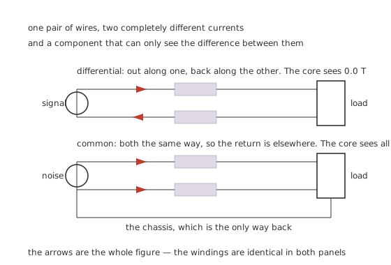
The arrows are the whole figure — the windings are identical in both panels.
The part is two matched windings on one ring, wound so that a current entering the first winding at its marked end and leaving the second at its marked end drives the core in opposite directions.
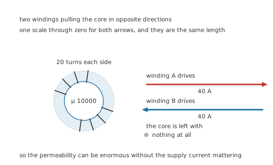
One scale through zero for both arrows, and they are the same length.
Worked example — What the core is left with
Take 20 turns per side on a ring of 40 square millimetres and a 60 mm path, at an illustrative permeability of 10000.
A supply current of 2.0 A through one winding applies 40 A of magnetomotive force. The same current returning through the other applies 40 A the other way.
The core is left with nothing, and it carries 0.0 T. That is why the ring's permeability can be 10000 — an absurd figure for any coil expected to carry amps — without the supply current mattering at all.
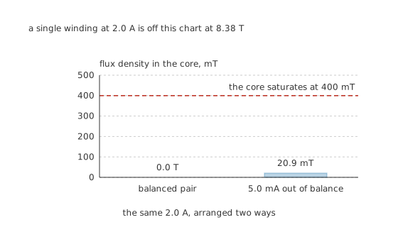
A single winding at 2.0 A is off this chart at 8.38 T.
Worked example — What a single winding would have needed
Put the same 2.0 A through one winding alone on that ring and the flux-density relation asks for 8.38 T — 20.9 times the material's illustrative 400 mT ceiling. It would have saturated at a few tens of milliamps.
Real windings are never perfectly matched, so put 5.0 mA of imbalance through the pair. That applies 100 mA of magnetomotive force and the core carries 20.9 mT, still 19.1 times below the ceiling.
The cancellation does not have to be exact. It only has to be good enough that what is left is small.
The permeability, the saturation flux density, the turns and the ring's dimensions here are invented illustrations. Real parts vary by more than an order of magnitude in every one of them.
Engineer
Two inductances from one component
Whether the two windings help or fight each other is the whole behaviour, and it comes out of one number: how tightly they are coupled.
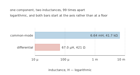
Logarithmic, and both bars start at the axis rather than at a floor.
Worked example — The number the whole part is judged on
That winding gives 3.35 mH per side. At an illustrative coupling of 0.98 the mutual inductance is 3.28 mH.
A common-mode current sees each winding's own inductance plus the mutual, because the other winding is helping: 6.64 mH.
A differential current sees the difference, because the other winding is opposing: 67.0 µH. That leftover is the leakage inductance, and the two differ by 99 times.
At 1.0 MHz that becomes 41.7 kΩ in the way of anything common-mode and 421 Ω in the way of everything else. The signal or the supply current walks through; the noise current runs into a wall.
The coupling coefficient is the specification. Push it from 0.98 towards unity and the leakage falls, the differential path gets cleaner, and the part becomes harder to make. Bifilar winding — the two wires laid side by side and wound together — gets the coupling high; sector winding, where each winding occupies its own half of the ring, deliberately does not.
Which is right depends on what you want the leakage to do. That sounds like a strange thing to say about an imperfection, and it is the next layer's subject.
Nothing above says anything about frequency, and frequency is where a choke's specification lives. The inductances here are the low-frequency figures, and a real part's impedance stops following them well before the megahertz mark: the high-permeability materials used for chokes lose their permeability early, the capacitance between the two windings starts shunting the very current the winding is blocking, and the part reaches a self-resonance of its own. A supplier's curve of common-mode impedance against frequency is the honest description, and a single millihenry figure is a headline. What matters for the reader here is the shape of the argument — a large inductance to one mode and a small one to the other — which survives all of that, because both figures move together as the material's permeability falls.
Professional
The leakage is not a defect
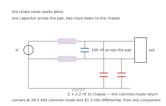
The choke never works alone.
Inductance in series with something only helps if there is a lower-impedance path for the current you are diverting. A choke on its own diverts nothing; it needs capacitors, and it needs two different sets of them because it is doing two different jobs.
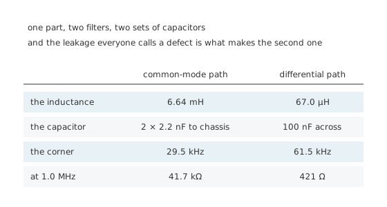
The leakage everyone calls a defect is what makes the second filter.
Worked example — Two corners from one part
The common-mode path uses the choke's 6.64 mH against two 2.2 nF capacitors from each conductor down to the chassis, which corners at 29.5 kHz.
The differential path uses the leakage, 67.0 µH, against a 100 nF capacitor across the pair. That corners at 61.5 kHz.
Two filters, two mechanisms, one component and three capacitors. Sector-wound parts are sold on their leakage for exactly this reason: a designer who needs differential filtering as well can get it free.
Choosing and fitting one
The chassis capacitors are the part of this that needs care. They bridge a live conductor to the metalwork a person can touch, so on a mains input they are a safety component with its own approval regime and its own failure requirements — safety capacitors covers what that means and why an ordinary ceramic of the same value is not a substitute. This lesson works a low-voltage example throughout and publishes no mains figures.
Current rating is about the winding, not the core. Since the core sees almost nothing when the currents balance, what limits a choke's current is copper heating and the small residual flux from the imbalance. A choke rated for several amps can be wound on a core that a plain inductor could not drive past milliamps.
Balance is what you are buying. Every asymmetry — a turn out of place, a lead of different length, a difference in stray capacitance to the core — turns a little of the differential current into common-mode current inside the filter, downstream of everything meant to stop it. This is called mode conversion and it sets the floor on how well any filter can work.
Data-line chokes are a different design. A choke on a signal pair has to leave the wanted signal untouched, so the leakage is minimised rather than exploited, and the parasitic capacitance between the windings matters as much as the inductance. Fitting a power-line choke on a fast data pair usually destroys the signal.
Where it goes decides whether it works. A choke belongs where the cable meets the board, before the noise has had a chance to couple onto anything else. A few centimetres of track on the wrong side of it is a few centimetres of antenna the choke cannot see.
One choke is often two chokes. Where a single stage cannot get enough attenuation, two chokes with different core materials in series cover different parts of the band, because a high-permeability material's own impedance falls away at high frequency exactly as a ferrite bead's rises.
Common mistakes
- Expecting it to filter the signal current — it cannot. A differential current meets only 67.0 µH of leakage against 6.64 mH common-mode, a factor of 99, and that asymmetry is the entire component.
- Fitting one without capacitors — series impedance diverts nothing unless the current has a better path. The two 2.2 nF chassis capacitors are what the common-mode current is being diverted into.
- Worrying about saturation from the supply current — with the pair balanced at 2.0 A the core carries nothing at all, and 5.0 mA of imbalance puts it at 20.9 mT, 19.1 times below the ceiling.
- Treating the leakage as pure loss — it is what makes the differential filter, cornering at 61.5 kHz against a 100 nF capacitor. Sector-wound parts are sold on having more of it.
- Substituting an ordinary capacitor for a chassis capacitor on a mains input — those parts bridge live metal to touchable metal and are approved for how they fail, not only for their value.
- Placing it after a length of track — anything between the connector and the choke is on the unfiltered side and radiates whatever the choke was fitted to catch.
Frequently asked questions
How can one component block one current and ignore another?
By being built so the two currents drive the core in opposite senses. A differential current's two magnetomotive forces cancel — here 40 A of ampere-turns each way, leaving 0.0 T in the core — while a common-mode current's add. The choke is not measuring anything; the geometry does the discrimination.
Why can the core have such a high permeability?
Because the supply current never magnetises it. A single winding carrying 2.0 A on this ring would demand 8.38 T, 20.9 times the material's 400 mT ceiling. With the pair balanced it demands nothing, so a permeability of 10000 is usable where it would be absurd in a plain inductor.
What is leakage inductance in a common-mode choke?
The part of each winding's inductance the other one does not cancel: L minus M, which is 67.0 µH here against 6.64 mH of common-mode inductance. It is what a differential current meets, and against a 100 nF capacitor it makes a differential filter cornering at 61.5 kHz.
Does the winding imbalance matter?
Only a little, for saturation. 5.0 mA of imbalance puts 20.9 mT in the core against a 400 mT ceiling. Imbalance matters for a second reason that has no such margin: an asymmetric choke turns some of the differential current into common-mode current downstream of itself, and no amount of inductance upstream can then remove it.
Can I use a common-mode choke on a data line?
Only one designed for it. A power-line choke has high inductance and high inter-winding capacitance, both of which wreck a fast signal. Data-line parts trade inductance away to keep the leakage and the stray capacitance small enough that the wanted signal survives.